Sign In
Upload
Manuals
Brands
Azbil Manuals
Valve Positioners
700 series
Azbil 700 series Manuals
Manuals and User Guides for Azbil 700 series. We have
3
Azbil 700 series manuals available for free PDF download: User Manual
Azbil 700 series User Manual (178 pages)
Smart Valve Positioner with Foundation Fieldbus
Brand:
Azbil
| Category:
Valve Positioners
| Size: 23 MB
Table of Contents
Table of Contents
7
Chapter 1. Structure of the 700 Series Control System
9
System Configuration
9
Structure of the Device and Description of each Part
11
Structure of the Device
11
Structure of Terminal Box
13
Display on the Local User Interface (LUI)
15
Chapter 2. Installation of the 700 Series
17
Usage Conditions
18
Selection Criteria for Installation Location
19
Installation Procedure
21
Mounting the 700 Series Onto the Actuator
21
Pneumatic Piping Connection
27
Electrical Wiring Connection
30
Cables
32
Cable Gland and Flameproof Universal Elbow for TIIS Flameproof Apparatus
34
Chapter 3. Operation of the 700 Series
39
Local User Interface (LUI)
40
Displays
42
Disp_Tb Display
43
Adjustment before Operation
52
Auto Setup
52
Zero Span Adjustment
55
Supply Bypass
58
Control Parameters
59
Starting Operation
61
Checking Fieldbus Operation
61
Preoperation Check
62
Chapter 4. Operations Using Fieldbus Communication
63
Fieldbus Communication Menus
63
Setup and Adjustment of Device
63
Process Variables
64
Auto Setup
64
Valve System
66
Control Configuration
67
Characterization
68
Final Value Cutoff
69
Units
69
Travel Calibration
70
Pressure Sensor Adjustment
71
Simulation
71
Test
72
Restore Factory Settings
73
Operator Action Records
73
Device Information
74
FF Option
74
Diagnostic Messages
75
Self-Diagnostic Messages
75
Control Valve Diagnostic Messages
77
Chapter 5. Troubleshooting
79
Troubleshooting
80
The Device Does Not Operate. (There Is no Output Air Pressure.)
80
The Control Valve Operates Abnormally (There Is Output Air Pressure.)
81
Display Transducer Block Does Not Switch to Auto (LUI Display Says "DISP_OOS.")
81
Adjustment Procedure When Hunting Occurs
82
Auto Setup Failure
83
Description of Messages
84
Chapter 6. Maintenance
91
A/M Switch
92
Replacement of Filter and Maintenance of Flow Restrictor
93
Cleaning the Flapper
94
Adjusting the Pilot Relay
95
Insulation Resistance Test
96
Adjustment Procedure When Using the Device with the Booster Relay Attached
97
Internal Block Diagram of the 700 Series
98
Resale Parts
98
Procedure to Change Switch Block
102
Procedure to Change Pilot Relay
103
Chapter 7. Notes on the Explosion-Proof 700 Series
105
TIIS Flameproof Model
106
ATEX Flameproof and Dust Ignition Protection
107
Iecex Flameproof and Dust Ignition Protection
109
FM Explosionproof/Dust Ignition Protection
111
FM Intrinsically Safe (IC) and Nonincendive
112
FMC Explosionproof/Dust Ignition Protection
115
NEPSI Flameproof/Dust Ignition Protection
116
KOSHA Flameproof
118
INMETRO Flameproof/Dust Ignition Protection
119
EAC Flameproof
121
ATEX Intrinsic Safety and Dust Ignition Protection
122
Iecex Intrinsic Safety and Dust Ignition Protection (FISCO)
123
Appendix A. LUI Display Example
125
Appendix B. Menu List
133
Appendix C. Parameter List
143
Appendix D Specifications
164
Appendix E Model Configuration Table
168
Appendix F. Outline Dimensional Drawing
169
Terms and Conditions
174
Advertisement
Azbil 700 series User Manual (162 pages)
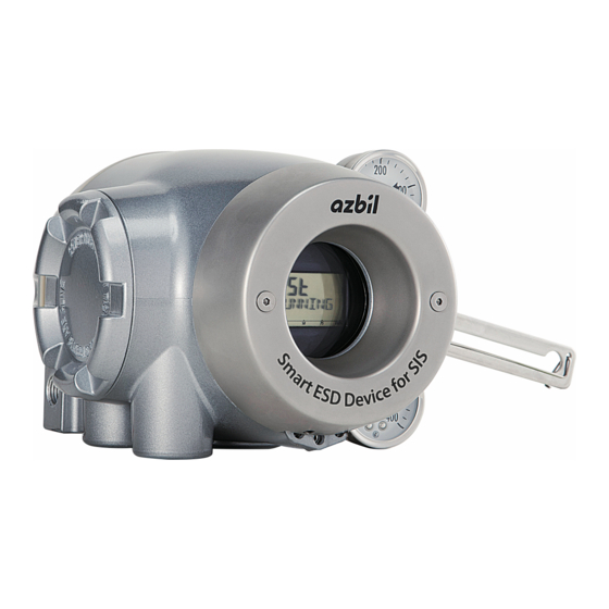
Smart ESD Device for Safety Instrumented Systems
Brand:
Azbil
| Category:
Measuring Instruments
| Size: 15 MB
Table of Contents
Table of Contents
7
Chapter 1 Structure of the Control System
11
Model Number Configuration
11
System Configuration
11
System Configuration (Model AVP7_2) Without Output Signal
12
In the Case of Current Signal Input
12
In the Case of Voltage Signal (0/24 V DC)
12
System Configuration with Travel Transmission (Model AVP7_1)
13
In the Case of Current Signal Input
13
In the Case of Voltage Signal (0/24 V DC)
13
System Configuration with Contact Output (Model AVP7_0)
14
In the Case of Current Signal Input
14
In the Case of Voltage Signal (0/24 V DC)
14
Structure of the Device and Description of each Part
15
Chapter 2 Installation
21
Usage Conditions
21
Selection Criteria for Installation Location
22
Installation Procedure
24
Attaching the 700 Series to the Actuator
24
Pneumatic Piping Connection
30
Electrical Wiring Connection
33
Input Signal and Output Signal Power
37
Cables (for Input or Output Signal)
38
Cable Gland and Flameproof Universal Elbow for TIIS Flameproof Apparatus
40
Chapter 3 Operation
45
Local User Interface (LUI)
45
Adjustment before Operation
49
Auto Setup
49
Zero/Span Adjustment
52
Supply Bypass
54
Partial Stroke Test (PST)
56
Control Parameters
58
Password
60
Starting Operation
61
Preoperation Check
61
Chapter 4 Operation with HART Communication
63
HART Communication
63
Setup and Adjustment of Device
64
Process Variables
64
Input Signal Range (Input Range) (Model AVP77_/78_ Current Signal Input)
66
Valve System
67
Control Configuration
68
Input Characterization
69
Travel Cutoff
70
Units
71
SIS Positioner Mode
71
Travel Calibration
72
Input Signal Calibration (Model AVP77_/78_ Current Signal Input)
73
Pressure Sensor Adjustment
74
Simulation
74
Adjustment of EPM Drive Signal (Pneumatic Modules)
74
Restore Factory Settings
74
Operator Action Records
75
Real Time Clock
75
Password
75
Device Information
75
Diagnostic Messages
78
Valve Diagnosis
79
PST (Partial Stroke Test)
80
FST (Full Stroke Test)
83
Chapter 5 Troubleshooting
85
If the Valve Does Not Close Fully (the Output Air Pressure Does Not Go down to 0)
85
If the Device Does Not Operate (no Output Air Pressure)
85
If the Valve Behaves Abnormally (Output Air Is Present)
86
Failure to Communicate with the Communicator
87
Adjustment Procedure When Hunting Occurs
87
Description of Messages
88
Chapter 6 Maintenance
95
A/M Switch
95
Replacement of Filter and Maintenance of Flow Constriction
98
Cleaning the Flapper
99
Adjusting the Pilot Relay
100
Insulation Resistance Test
101
Adjustment Procedure When Using the Device with a Booster Relay Attached
102
List of Default Values for Internal Data
103
Internal Block Diagram of the 700 Series
104
Replacement Parts
105
Procedure for Changing Switch Block
108
Procedure for Changing the Pilot Relay
109
Chapter 7 Notes on Explosion-Proof Structure
111
TIIS Flameproof Model
112
Iecex Flameproof and Dust Ignition Protection
113
FM Explosion-Proof / Dust Ignition Protection
115
FM Intrinsically Safe Explosion-Proof Type (IC) and Non-Incendive Type
116
FMC Explosion-Proof / Dust Ignition Protection
121
NEPSI Flameproof / Dust Ignition Protection
122
KOSHA Flameproof Type
125
INMETRO Flameproof / Dust Ignition Protection
126
EAC Flameproof
128
ATEX Intrinsic Safety and Dust Ignition Protection
129
Iecex Intrinsic Safety and Dust Ignition Protection
130
Appendix A LUI Display Examples
131
Appendix B Menu List
143
Azbil 700 series User Manual (154 pages)
Smart Valve Positioner with HART communication protocol
Brand:
Azbil
| Category:
Valve Positioners
| Size: 14 MB
Table of Contents
Table of Contents
7
Chapter 1 Structure of the 700 Series Control System
9
System Configuration
9
System Configuration Without Motion Transmission
10
System Configuration with Motion Transmission
10
Structure of the Device and Description of each Part
11
Structure of the Device
11
Structure of Terminal Box
13
Display on the Local User Interface (LUI)
15
Chapter 2 Installation of the 700 Series
17
Usage Conditions
18
Selection Criteria for Installation Location
19
Criteria for Instrumentation Air
19
Installation Procedure
21
Mounting the 700 Series Onto the Actuator
21
Pneumatic Piping Connection
28
Electrical Wiring Connection
31
Input Signals and Travel Transmission Power
33
Cables
34
Cable Gland and Flameproof Universal Elbow for TIIS Flameproof Apparatus
36
Chapter 3 Operation of the 700 Series
41
Local User Interface (LUI)
42
Adjustment before Operation
45
Auto Setup
45
Zero Span Adjustment
49
Supply Bypass
52
Control Parameters
53
Password
55
Starting Operation
56
Preoperation Check
56
Chapter 4 Operation with HART Communication
57
Operation with HART Communication
57
Setup and Adjustment of Device
58
Process Variables
58
Auto Setup
59
Input Range
61
Valve System
61
Control Configuration
62
Input Characterization
64
Travel Cutoff
64
Units
65
Travel Calibration
66
Input Calibration
68
Pressure Sensor Adjustment
68
Simulation
68
Adjustment of EPM Drive Signal (Pneumatic Modules)
69
Restore Factory Settings
69
Operator Action Records
69
Real Time Clock
69
Password
69
Device Information
70
Option
72
Diagnostic Messages
73
Control Valve Diagnostic Messages
75
Chapter 5 Troubleshooting
77
The Device Does Not Operate. (There Is no Output Air Pressure.)
78
The Control Valve Operates Abnormally (There Is Output Air Pressure.)
78
Failure to Communicate with the Communicator
78
Adjustment Procedure When Hunting Occurs
79
Auto Setup Failure
80
Description of Messages
81
Chapter 6 Maintenance
87
A/M Switch
88
Replacement of Filter and Maintenance of Flow Restriction
90
Cleaning the Flapper
91
Adjusting the Pilot Relay
92
Insulation Resistance Test
93
Adjustment Procedure When Using the Device with the Booster Relay Attached
94
List of Default Values for Internal Data
95
Internal Block Diagram of the 700 Series
96
Resale Parts
97
Procedure to Change Switch Block
101
Procedure to Change Pilot Relay
102
Chapter 7 Notes on the Explosion-Proof 700 Series
103
TIIS Flameproof Model
104
ATEX Flameproof and Dust Ignition Protection
105
Iecex Flameproof and Dust Ignition Protection
107
FM Explosionproof / Dust Ignition Protection
109
FM Intrinsically Safe (IC) and Nonincendive
110
FMC Explosionproof / Dust Ignition Protection
115
NEPSI Flameproof / Dust Ignition Protection
116
KOSHA Flameproof
118
INMETRO Flameproof / Dust Ignition Protection
119
EAC Flameproof
121
ATEX Intrinsic Safety and Dust Ignition Protection
122
Iecex Intrinsic Safety and Dust Ignition Protection
123
Appendix A LUI Display Example
125
Appendix B Menu List
131
Appendix C Specification
139
Appendix D Model Selection
143
Appendix E Outline Dimensional Drawing
145
Advertisement
Advertisement
Related Products
Azbil 100 Series
Azbil AVP100
Azbil AVP102
Azbil AVP200
Azbil AVP201
Azbil AVP202
Azbil AVP300
Azbil AVP301
Azbil AVP302
Azbil AVP701
Azbil Categories
Controller
Control Unit
Measuring Instruments
Transmitter
Security Sensors
More Azbil Manuals
Login
Sign In
OR
Sign in with Facebook
Sign in with Google
Upload manual
Upload from disk
Upload from URL