Table of Contents
Advertisement
SteamCraft 10
Convection Steamer
SERVICE
MANUAL
Printed 3/93
UNITED STATES
1333 East 179th St.. Cleveland, Ohio 44110 Phone: (216) 451-4900 •
Telex: 98-0546 • FAX: (216) 481-3782
Cleveland Range
®
Cleveland Range, Inc.
MODELS: 24-CEA-10, & 24-CGA-10
CANADA
Garland Commercial Ranges
1177 Kamato Road
Mississaugha, Ontario. Canada L4W1X4
Phone: (416) 624-0260 - FAX: (416) 624-0623
Advertisement
Table of Contents
Troubleshooting

Subscribe to Our Youtube Channel
Related Manuals for Cleveland SteamCraft 10


Summary of Contents for Cleveland SteamCraft 10
- Page 1 MODELS: 24-CEA-10, & 24-CGA-10 Printed 3/93 Cleveland Range, Inc. UNITED STATES CANADA 1333 East 179th St.. Cleveland, Ohio 44110 Phone: (216) 451-4900 • Garland Commercial Ranges 1177 Kamato Road Telex: 98-0546 • FAX: (216) 481-3782 Mississaugha, Ontario. Canada L4W1X4 Phone: (416) 624-0260 - FAX: (416) 624-0623...
- Page 2 The warranty printed to the left specifies the owner/user's responsibility for proper installation, operation, and maintenance of the SteamCraft 10. If these responsibilities are not met, toe Limited Warranty and/or Extended Limited Warranty coverage may be adversely affected. The following table is provided to assist the owner/user in meeting these responsibilities.
-
Page 3: Table Of Contents
Water Supply System Selecting The Operating Location INSTALLATION INSTRUCTIONS Unpacking & Inspection Shipping Damage Instructions Position & Level The SteamCraft 10 Adjustable Leveling Legs Positioning & Leveling Install Slide Racks Install & Connect The Free Air Vented Drain Lines Exhaust Hood Ventilation – All Models... - Page 4 Page ii SteamCraft 10 Service Manual Models 24-CGA-10 0 and 24-CEA-10 Table of Contents (continued) Chapter Page Installation Checks Operating Tests Operating Test Preparation Blowdown Inspection Procedure Operating Test Procedures Timer Test Procedures – Key Pad Control Panel Timer Test Procedures – Dial Timer Control Panel CHAPTER 3.
-
Page 5: Models 24-Cga-10 And 24-Cea-10
Models 24-CGA-10 and 24-CEA-10 SteamCraft 10 Service Manual Page iii Table of Contents (continued) Chapter Page Start the Steam Supply Inspect the Cooking Compartment Preheat the Cooking Compartment(s) Place Food into The Cooking Compartment(s) Select the Operating Mode Timed Cooking Procedure... - Page 6 Condenser and Drain Functions Condenser Operation Drain Valve Functions Shutdown, Steam Generator And Float Cylinder Rise Functions STEAMCRAFT 10 ELECTRICAL CIRCUITS – Model 24-CEA-10 High Voltage Circuit 120 VAC Circuit STEAMCRAFT 10 ELECTRICAL CIRCUITS – Model 24-CGA-10 STEAMCRAFT 10 TIMER CIRCUITS...
- Page 7 Models 24-CGA-10 and 24-CEA-10 SteamCraft 10 Service Manual Page v Table of Contents (continued) Chapter Page COMPONENT TESTING FUNDAMENTALS Visual Check Connections and Wiring Solenoid Valves General Considerations Normally Open And Normally Closed Valves And Contacts Water Pressure and Control Valves...
- Page 8 CT:23 & CT:24 Heater & Dryer Elements – Model 24-CEA-10 CT:25 Relay R-1 – Model 24-CEA-10 Burner Ignition & Control System Components – Model 24-CGA-10 CHAPTER 7. ILLUSTRATED PARTS LISTS INTRODUCTION Parts Differences Among SteamCraft 10 Steamers Electrical Schematics And Wiring Diagrams Ordering Parts CHAPTER 8. IGNITION MODULE INTRODUCTION HONEYWELL &...
-
Page 9: Chapter 1. Product Identification
Page 1 CHAPTER 1. PRODUCT IDENTIFICATION Cleveland Range, Inc. assigns two product identification numbers to each SteamCraft 10: a model number and a serial number. The model number identifies the product characteristics. The serial number identifies the indi- vidual unit. - Page 10 Page 2 Chapter 1, SteamCraft 10 Service Manual Models 24-CGA-10, 24-CGP-10, 24-CEA-10, 24-CEP-10 Figure 1-1. SteamCraft 10 Product information Plates Printed 3/93 Cleveland Range, Inc.
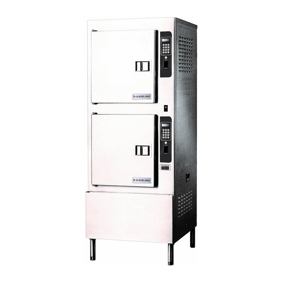
- Page 11 Models 24-CGA-10, 24-CGP-10, 24-CEA-10, 24-CEP-10 SteamCraft 10 Service Manual, Chapter 1 Page 3 Figure 1-2. SteamCraft 10, Models 24-CGA-10 and 24-CEA-10 with Key Pad Control Panel (Sheet 1 of 4) Cleveland Range, Inc. Printed 3/93...
- Page 12 Chapter 1, SteamCraft 10 Service Manual Models 24-CGA-10, 24-CGP-10, 24-CEA-10, 24-CEP-10 Page 4 Figure 1-2. SteamCraft 10, Models 24-CGP-10 and 24-CEP-10 with Key Pad Control Panel (Sheet 2 of 4) Printed 3/93 Cleveland Range, Inc.
- Page 13 Models 24-CGA-10, 24-CGP-10, 24-CEA-10, 24-CEP-10 SteamCraft 10 Service Manual, Chapter 1 Page 5 Figure 1-2- SteamCraft 10, Models 24-CGA-10 and 24-CEA-10 with Dial Timer Control Panel (Sheet 3 of 4)
- Page 14 Page 6 Chapter 1, SteamCraft 10 Service Manual Models 24-CGA-10, 24-CGP-10, 24-CEA-10, 24-CEP-10 Figure 1-2. SteamCraft 10, Models 24-CGP-10 and 24-CEP-10 with Dial Timer Control Panel (Sheet 4 of 4)
-
Page 15: Chapter 2. Installation Instructions
INTRODUCTION This chapter is a guide for installation of the SteamCraft 10, model numbers 24- CGA-10,24-CGP-10,24-CEA-10 and 24-CEP-10. This guide is for use by qualified professionals, and does not include all procedures and precautions in the common domain of licensed plumbers, pipe fitters, and electricians, or experienced food service equipment installers. -
Page 16: Installation Overview
INSTALLATION OVERVIEW SteamCraft 10 installation is presented in two parts: preparation and instal- lation. Table 2-1 and Figure 2-1 provide an overview of installation process. Figure 2-1, Schematic Installation Diagram, illustrates the utility lines and connections required to install the SteamCraft 10. - Page 17 Models 24-CGA-10, 24-CGP-10. 24-CEA-10, 24-CEP-10 SteamCraft 10 Service Manual Chapter 2 Page 9 INSTALLATION DIAGRAM NOTES 1 . For each unit, the installer must provide a ground con- 7. Run a single water line between the main cold water supply nection and a separate fused disconnect switch.
-
Page 18: Preparation For Installation
1. Leave packaged components inside the shipping canon or cooking com - partment. 2. Keep the SteamCraft 10 dean by covering it with a plastic tarp or drop cloth. 3. Do not store other items on top of the SteamCraft 10. -
Page 19: Water Quality Requirements
Range's warranty coverage of the SteamCraft 10. As with any steam generating equipment, poor water quality degrades SteamCraft 10 performance. If feed water is low in Total Dissolved Solids (TDS) and free of particulate matter, the steam generator, heating element, and valves of me Steam Craft 10 will give years of trouble -free service with a minimum of maintenance. - Page 20 Page 12 Chapter 2, SteamCraft 10 Service Manual Models 24-CGA-10, 24-CGP-10, 24-CEA-10, 24-CEP-10 Figure 2-2- SteamCraft 10 Dimensions and Clearances Model 24-CGA-10 (Sheet 1 of 4) Printed 3/93 Cleveland Range, Inc.
- Page 21 Models 24-CGA-10, 24-CGP-10, 24-CEA-10, 24-CEP-10 SteamCraft 10 Service Manual, Chapter 2 Page 13 Figure 2-2- SteamCrafi 10 Dimensions and Clearances Model 24-CGP-10 (Sheet 2 of 4) Cleveland Range, Inc. Printed 3/93...
- Page 22 Page 14 Chapter 2, SteamCraft 10 Service Manual Models 24-CGA-10, 24-CGP-10, 24-CEA-10, 24-CEP-10 Figure 2-2- SteamCraft 10 Dimensions and Clearances Model 24-CEA-10 (Sheet 3 of 4) Printed 3/93 Cleveland Range, Inc.
- Page 23 Models 24-CGA-10, 24-CGP-10, 24-CEA-10, 24-CEP-10 SteamCraft 10 Service Manual, Chapter 2 Page 15 Figure 2-2. SteamCraft 10 Dimensions and Clearances Model 24-CEP-10 (Sheet 4 of 4) Cleveland Range, Inc. Printed 3/93...
-
Page 24: Softened, Treated, Or Filtered Water
Models 24-CGA-10, 24-CGP-10, 24-CEA-10, 24-CEP-10 Softened, Treated, or Filtered Water Do not use softened or chlorinated water in the SteamCraft 10 steam generator- If the water supply is treated or softened either by the water company or on the premises, it may contain chlorine or various salts. -
Page 25: Selecting The Operating Location
7. Installation of an exhaust hood over the unit may be required by local, state, and/or national codes. Refer for Exhaust Hood Requirements - All Models on page 10. If the SteamCraft 10 cannot be installed under an existing hood, check the exhaust hood venting requirements for a suitable hood over the operating location. -
Page 26: Installation Instructions
Models 24-CGA-10, 24-CGP-10, 24-CEA-10, 24-CEP-10 INSTALLATION INSTRUCTIONS After selecting the operating location, the SteamCraft 10 can be unpacked, positioned, and installed. After Final Setup and Checkout, the SteamCraft 10 will provide years of reliable operation. CAUTION Malfunctions and equipment damage may result from improper mounting. -
Page 27: Shipping Damage Instructions
Page 19 Shipping Damage Instructions If shipping damage to the SteamCraft 10 is discovered or suspected, observe the following guidelines in preparing a shipping damage claim. • Write down a description of the damage or the reason for suspecting damage as soon as it is discovered. -
Page 28: Install Slide Racks
SteamCraft 10 Steamer with free air venting. Furnishing and installing the drain lines and fittings is the responsibility of the owner and/or installer. Figure 2-6 illustrates a drain layout recommended by Cleveland Range. Observe the following instructions to determine the pipe size, the number of... - Page 29 Models 24-CGA-10, 24-CGP-10, 24-CEA-10, 24-CEP-10 Page 21 SteamCraft 10 Service Manual, Chapter 2 WARNING DEATH, INJURY, AND EQUIPMENT DAMAGE could result from improper installation of the drain outlet lines. Improper installation of these lines could void the SteamCraft 10 Steamer warranty. The following...
-
Page 30: Exhaust Hood Ventilation All Models
1. The SteamCraft 10 gas flue (G) must be vented in compliance with all local, state, and national codes for venting gas-fired appliances. Steam venting must comply with the state and local codes where applicable. -
Page 31: Connect Electrical Line
Page 23 Figure 2-8. Recommended Electrical Layout 5. There should be a sufficient length of flexible conduit between the SteamCraft 10 connector and the wall so the unit can be moved for service 6. Each steamer must be electrically grounded by the installer in accordance with the National Electric Code, ANSI/NFPA No. -
Page 32: Install Water Supply Lines
3. Do not connect the SteamCraft 10 to a softened or treated water supply which adds chlorine or chloride salts to the water. Refer to Softened, Treated, or Filtered Water on page 16 for details. - Page 33 Range recommends the plumbing layout illustrated in Figure 2-10. This is a single water line from the main cold water supply to the tee just outside the SteamCraft 10. The two separate lines from the tee to the steam generator and condenser/blowdown connections are comparatively short.
-
Page 34: Connect Water Supply Lines
SteamerGard manual, and Connect Water Supply Lines, following. The water supply connections are located under the SteamCraft 10, as shown in Figure 2-2. Connect the water supply lines to the Steam Craft 10 by... -
Page 35: Untreated Water Connection (Without Steamgard)
1. Install the gas supply lines in accordance with local codes and/or the National Fuel Gas Code, ANSI Z223.1-(latest edition). 2. Refer to Figure 2-14 for Cleveland Range recommended layout of the gas supply lines. Refer to Figure 2-2, Dimensions and Clearances for pressure data and... -
Page 36: Leak-Testing Gas Supply Lines
In order to protect the automatic gas control valve from condensation, the drip leg should be close to the SteamCraft 10 gas connection. 5. If natural gas pressure exceeds 14" water column, a pressure regulating valve must be installed in the gas supply plumbing to reduce the pressure to within the limits specified in Gas Supply Requirements, on page 10. -
Page 37: Pressure Testing The Gas Supply Lines
1. A gas lines and fittings assembled during installation are outside of the SteamCraft 10. Check these connections for proper tightness. 2. Prepare the Steam Craft 10 valves and connections for the test pressure being used. -
Page 38: Bleed Air From The Gas Supply Lines
Bleed the gas supply line by the following procedure. 1. Turn off electrical power to the SteamCraft 10 at both the panel ON/OFF switch (Figure 2-16), and the main disconnect switch (Figure 2-8, Rec- ommended Electrical Layout). -
Page 39: Burner Ignition Test (Gas-Fired Models Only)
8. Leave the electrical power OFF at both the main disconnect switch and the control panel ON/OFF switch. 9. The SteamCraft 10 is now ready for operational testing. • If this test is part of initial installation, perform the Burner Ignition Test before performing the Operating Tests. - Page 40 ON position. d. Turn the main manual gas shut-off valve to the ON position. 2. Turn ON the electrical power to the SteamCraft 10 at the main disconnect switch. NOTE: When initial power is supplied to the SteamCraft. 10 with the ON/OFF switch in the OFF position, a 3-minute blowdown cycle starts.
-
Page 41: Final Setup & Checkout
The Final Setup and Checkout procedures prepare a recently installed or repaired SteamCraft 10 for operation. The procedures check proper electrical, gas, water, and drain connections to the SteamCraft 10, and verify basic steamer operation. Read through all pans of this procedure before starting. -
Page 42: Operating Tests
Except when the instructions specify upper or lower compartments, the controls of either or both panels can be used. • The SteamCraft 10 control panels have either a Key Pad Timer or a Dial Timer. The operating difference between the Dial and Key Pad Control Panels is significant only in timed mode. -
Page 43: Blowdown Inspection Procedure
Operating Test Procedures 1. Verify that electrical power to the SteamCraft 10 is turned OFF at the panel ON/OFF switch, and turned ON at the main dis connect switch. 2. Set both upper and lower compartment TIMED/MANUAL switches to the TIMED position. - Page 44 8. With the SteamCraft 10 in Manual Cooking Mode, the unit will steam continuously until turned off, or set to Timed Cooking Mode. Set both upper and lower compartment control panels for MANUAL operation.
-
Page 45: Timer Test Procedures - Key Pad Control Panel
Models 24-CGA-10, 24-CGP-10, 24-CEA-10, 24-CEP-10 SteamCraft 10 Service Manual, Chapter 2 Page 37 a. Close the Steam Craft 10 manual water supply valve. Observe the steam generator float cylinders while steaming continues. b. As water steams out of the generator, the water level drops below the safety level sensor. -
Page 46: Timer Test Procedures - Dial Timer Control Panel
Press the START/STOP key to silence the buzzer. f. After about 30 seconds, steam stops entering the cooking compartment 6. Turn the SteamCraft 10 off by pressing the OFF (bottom) end of the ON/OFF switch. The red indicator on the switch turns off immediately, and the automatic blowdown cycle starts. - Page 47 Figure 2-19. Steam Generator Controls Pressure Units Only 6. Turn the SteamCraft 10 off by pressing the OFF (bottom) end of the ON/OFF switch. The red indicator on the switch turns off immediately. and the automatic blowdown cycle starts. DO NOT turn off the power at the main disconnect switch until blowdown is complete.
-
Page 48: Chapter 3. Operation
CHAPTER 3. OPERATION INTRODUCTION The SteamCraft 10 is as safe and easy to operate as a touch tone phone or a kitchen timer. To use the steamer safely and effectively, each operator must read and understand this chapter completely before starting operation. The owners and operators of the SteamCraft 10 should retain these instructions in an easily accessible location for future reference and training. - Page 49 4. Follow the instructions for steamer maintenence in Chapter 4. 5. Before each use of the SteamCraft 10, inspect the drain and screen for blockage. Inspect the door gasket assembly, and slide racks for proper installation and cleanliness.
-
Page 50: Burner Lighting
BURNER LIGHTING DO NOT TRY TO LIGHT THE BURNERS OR PILOT WITH A FLAME. THE PILOT AND BURNERS ARE SELF-IGNITING. The SteamCraft 10 has an electronic ignition system which automatically lights the pilot and burners, senses the flame, and controls gas flow. This provides precise burner control, safety ignition, and shutdown features. -
Page 51: Steam Generator Blowdown
SteamerGard installed and the supply water is hard. MAIN DISCONNECT SWITCH Usually the SteamCraft 10 main disconnect switch is left on. If the main disconnect switch is in the off position, turn it on as follows. - Page 52 Models 24-CGA-10, 24-CGP-10, 24-CEA-10, 24-CEP-10 SteamCraft 10 Service Manual, Chapter 3 Page 45 KEY PAD CONTROL PANEL On atmospheric units, the ON/OFF switch both energizes the unit controls and SUMMARY starts the water fill and steam generator preheating cycle. On pressurized units, the ON/OFF switch energizes the unit controls and starts the water fill cycle.
-
Page 53: Cooking Operations Key Pad Control Panel
• Timed Mode. Set the Timer for continuous steam cooking until the timer counts down and stops the steaming cycle. 7. Remove food from the cooking compartment(s). 8. Power Off (Automatic Blowdown) 9. At end of each day or shift, shut down and clean the SteamCraft 10. -
Page 54: Start Steam Supply
Page 47 Power ON (Automatic Fill) When the SteamCraft 10 is turned on, it automatically fills the steam generator with water. Use this procedure at the beginning of a shift to prepare the steamer for operation without Starting steam generation. When ready to start steam cooking, begin either the Timed or Manual Operating Procedure. -
Page 55: Preheat The Cooking Compartments
• Between cooking batches to maintain cooking temperature in the compartment. Preheat the SteamCraft 10 by the following procedure. 1. BEFORE PREHEATING, inspect and clean the compartment. After preheating, the compartment will be too hot to inspect and clean safely. Refer to Inspect the Cooking Compartment on page 47. -
Page 56: Place Food Into The Cooking Compartment(S)
6. When the timer reaches zero. a buzzer sounds continuously. Press the START/STOP key to silence the buzzer. 7. Preheat is now comple te. The SteamCraft 10 steam generating functions are at full capacity, and the cooking compartment is at proper cooking temperature. -
Page 57: Timed Cooking Procedure
Page 50 Chapter 3, SteamCraft 10 Service Manual Models 24-CGA-10, 24-CGP-10, 24-CEA-10, 24-CEP-10 TIMED MODE: In timed mode, the timer starts and stops the steaming operations. Use the timed mode for: • Unattended cooking for a specific amount of time. -
Page 58: Manual Cooking Procedure
Models 24-CGA-10, 24-CGP-10, 24-CEA-10, 24-CEP-10 SteamCraft 10 Service Manual, Chapter 3 Page 51 All seconds method: Change the 1.5 minutes to 90 seconds and press 9 0. The display reads 00:90 when set for 1.5 minutes. When the timer starts, the display automatically changes to minutes and seconds (01:30). -
Page 59: Power Off (Automatic Blowdown)
Chapter 3, SteamCraft 10 Service Manual Models 24-CGA-10, 24-CGP-10, 24-CEA-10, 24-CEP-10 Follow this procedure when cooking with the SteamCraft 10 in manual mode. 1. Refer to Inspect the Cooking Compartment on page 47. Inspect and clean the drain and cooking compartment as required. -
Page 60: Blowdown Procedure
Shut Down and Cleaning procedure. Blowdown Procedure When the SteamCraft 10 is turned off, the blowdown cycle starts and runs automatically. The complete cycle takes approximately 3 minutes. 1. Press the OFF (bottom) end of the ON/OFF switch to turn off the SteamCraft 10. - Page 61 Page 54 Chapter 3, SteamCraft 10 Service Manual Models 24-CGA-10, 24-CGP-10, 24-CEA-10, 24-CEP-10 abrasive cleaning compounds or steel wool. Rinse inside of steamer compartment with clean water. WARNING Let rinse water drain through compartment drain opening. If water does not drain freely, drain lines must be cleaned before cooking again.
-
Page 62: Dial Timer Control Panel Summary
Models 24-CGA-10, 24-CGP-10, 24-CEA-10, 24-CEP-10 SteamCraft 10 Service Manual, Chapter 3 Page 55 DIAL TIMER CONTROL PANEL SUMMARY On atmospheric units, the ON/OFF switch both energizes the unit controls and starts the water fill and steam generator preheating cycle. On pressurized units, the ON/OFF switch energizes the unit controls and starts the steam generator water fill cycle. -
Page 63: Cooking Operations - Dial Timer Control Panel
Steam Craft 10. Power ON (Automatic Fill) When the SteamCraft 10 is turned on, it automatically fills the steam generator with water. Use this procedure at the beginning of a shift to prepare the steamer for operation without starting steam generation. When ready to start steam cooking, begin either the Timed or Manual Operating Procedure. -
Page 64: Start The Steam Supply
Preheat the Cooking Compartment(s) Cleveland Range recommends preheating the SteamCraft 10 cooking com- partments to maintain accurate, efficient cooking times. Preheating is espe- cially recommended for the first cooking cycle after power on, and if there has been a long idle period between cooking cycles. -
Page 65: Place Food Into The Cooking Compartment(S)
4. Close the steamer door, and proceed to Select and Start the Operating Mode. The SteamCraft 10 has two cooking modes: Manual and Timed. Select The Operating Mode MANUAL MODE: In manual mode the operator starts and stops the steaming operations. Use the manual cooking mode for: •... -
Page 66: Manual Cooking Procedure
Models 24-CGA-10, 24-CGP-10, 24-CEA-10, 24-CEP-10 SteamCraft 10 Sevice Manual, Chapter 3 Page 59 • The ON/OFF switch is in the ON (top) position. • The TIMED/MANUAL switch is in the TIMED (top) position. • The timer dial points to 0. -
Page 67: Power Off (Automatic Blowdown)
1. Carefully open the cooking compartment. Doors and remove the pans from the slide racks. 2. If the SteamCraft 10 will be used again in a few minutes, shut the door to maintain the cooking compartment temperature. 3. If another use is not planned for more than half an hour, leave the cooking compartment door slightly open to reduce internal pressure while the steam condenses and the compartment cools. -
Page 68: Shut Down And Cleaning (At End Of Day Or Shift)
Models 24-CGA-10, 24-CGP-10, 24-CEA-10, 24-CEP-10 SteamCraft 10 Service Manual, Chapter 3 Page 61 Shut Down and Cleaning (At end of day or shift) This procedure must be performed at the end of each day or shift to maintain warranty coverage. -
Page 69: Chapter 4. Preventative Maintenance And Troubleshooting
The SteamCraft 10 is equipped with a drain screen in the back of th cooking compartment. Never operate the steamer without the screen in place. The Cleveland Range, Inc. -
Page 70: Monthly Maintenance
Steam generator should be descaled at least once a month, depending on scale buildup. If you have serious steam generator scale buildup, install a water treatment system for the steamer. Cleveland Range, Inc. recommends use of the descaling kit, part number 104394, which consist of liquid phosphoric acid. - Page 71 Models 24-CGA-10, 24CGP-10, 24-CEA-10, 24-CEP-10 SteamCraft 10 Service Manual, Chapter 4 Page 65 WARNING The liquid phosphoric acid in descaling kit 104394 can be harmful it not handled properly. Follow these basic safety rules for handling and using acid. Wear protective clothing when mixing or applying chemical cleaners.
- Page 72 Page 66 Chapter 4, SteamCraft 10 Service Manual Models 24-CGA-10, 24CGP-10, 24-CEA-10, 24-CEP-1C b. Remove 1/2-inch pipe plug from the top of the steam generator. See Figure 4-2. WARNING DEATH, BURNS, OR ELECTRIC SHOCK can occur by touching electrical components and wires inside the access cover when the main disconnect switch is in the on position.
-
Page 73: Yearly Maintenance
ON/OFF switch ON, waiting for the steam generator to fill (about 3-4 minutes), and then pressing the ON/OFF switch to OFF. 21. After the steam generator has drained, the SteamCraft 10 is ready for operation as desired. NOTE: Contact service representative or manufacturer for descaling kits or for information on descaling procedures. - Page 74 Page 68 Chapter 4, SteamCraft 10 Service Manual Models 24-CGA-10, 24CGP-10, 24-CEA-10, 24-CEP-10 OPERATOR'S TROUBLESHOOTING GUIDE This troubleshooting guide includes a list of symptoms that and easiest to repair listed first. The third column also refers to may be encountered during routine operation and maintenance.
- Page 75 SteamCraft 10 Service Manual, Chapter 4 Models 24-CGA-10, 24CGP-10, 24-CEA-10, 24-CEP-10 Page 69 OPERATOR'S TROUBLESHOOTING GUIDE (continued) PROBLEM POSSIBLE CAUSE REMEDY/REFERENCE Steam and/or water draining around Drain clogged or covered. Clean drain with USDA approved drain cleaner. compartment door. Door gasket or door parts worn.
-
Page 76: Troubleshooting Notes
2. Proper installation of the Steam Craft 10 is the responsibility of the owner or installer. Refer to Cleveland Range. Inc. warranty on the inside front cover. 3. Repairs to external plumbing should be done by a Licensed Plumber. -
Page 77: Chapter 5. Component And Circuit Functions
Service technicians unfamiliar with SteamCraft 10 operating functions should study this section in conjunction with Chapter 3. Service technicians already familiar with the SteamCraft 10 may use this section to refresh their knowledge of the component functions, or proceed directly to the component testing in Chapter 6. -
Page 78: Control Panel Type
These units do not have a compartment thermostat. THEORY OF OPERATION When troubleshooting and testing SteamCraft 10 components, an understanding of overall SteamCraft 10 operation is helpful. This section describes equipment and component functions tha occur during SteamCraft 10 operation-... - Page 79 Models 24-CGA-10 and 24-CEA-10 SteamCraft 10 Service Manual , Chapter 5 Page 73 Water in The Float and Water in The Float and Steam Generator is Below Steam Generator Is Above The Safe Operating Level. The Lower Float Switch Water in The Float and...
-
Page 80: Steam Generator Preheating
Models 24-CGA-10 and 24-CEA-10 SteamCraft 10 Service Manual, Chapter 5 Page 74 Figure 5-3. Steam Generator Preheating The heating components cycle Preheating does not start The heating components with the Preheat Thermostat until the water has reached turn on when water is above T'stat OPEN - Heater OFF the Safe Operating Level. -
Page 81: Steaming Functions For Model 24-Cea-10
Models 24-CGA-10 and 24-CEA-10 SteamCraft 10 Service Manual , Chapter 5 Page 75 Steaming Functions For Model 24-CEA-10 The steaming cycle heats water in the steam generator to steaming temperature (above 217°F), and fills the cooking compartment with steam. The steaming cycle operates simultaneously with the water fill cycle to maintain a continuous flow of cooking steam. -
Page 82: Steaming Functions For Model 24-Cga-10
Models 24-CGA-10 and 24-CEA-10 Page 76 SteamCraft 10 Service Manual, Chapter 5 stops its preheat cycle and the starts a steaming cycle. The upper com- partment continues MANUAL Steaming. Refer to Figure 5-5. 1. The TIMED setting by-passes the Preheat Thermostat, and energizes the lower steaming circuit through the timer circuit. - Page 83 Models 24-CGA-10 and 24-CEA-10 SteamCraft 10 Service Manual, Chapter 5 Page 77 A. When the ON/OFF switch is first set to ON the water fill and preheat cycles start and operate as described on pages 72 and 74. B. When the lower TIMED/MANUAL switch is set to MANUAL, the lower compartment steaming circuits are energized directly.
- Page 84 Models 24-CGA-10 and 24-CEA-10 Page 78 SteamCraft 10 Service Manual, Chapter 5 When the upper cooking compartment is set for a period of timed steaming, the upper compartment steaming circuits are energized through the timer circuit. The lower compartment continues MANUAL steaming as described in step B.
-
Page 85: Gas Burner Ignition And Combustion Functions Model 24-Cga-10
Burner Ignition - 24-CGA-10 Burner Ignition and Control System The SteamCraft 10's Intermittent Pilot (IP) Ignition and Control System is comprised of White Rogers and Honeywell components. The associated White Rogers and Honeywell manuals are duplicated in Chapter 8. All troubleshooting, maintenance and repair of the IP Burner Control System Components should be done according to these manuals. -
Page 86: Condenser And Drain Functions
SteamCraft 10 Service Manual, Chapter 5 Condenser and Drain Functions The SteamCraft 10 drain piping has five branches: one from each steam generator, one from each cooking compartment, and one from the door gutter in the front panel. All five branches combine at the drain fitting: which exits through the bottom of the unit. -
Page 87: Drain Valve Functions
Models 24-CGA-10 and 24-CEA-10 SteamCraft 10 Service Manual Chapter 5 Page 81 Drain Valve Functions The drain solenoid valve, acting with the water fill valve, performs three critical steam generator functions. The valve directs water flow to fill. drain. and rinse the steam generator. -
Page 88: Shutdown, Steam Generator And Float Cylinder Rise Functions
Page 82 SteamCraft 10 Service Manual, Chapter 5 Models 24-CGA-10 and 24-CEA-10 Shutdown, Steam Generator and Float Cylinder Rinse Functions Refer to Figure 5-14. Typically, when the Steam Craft 10 is shut down at the end of a shift, only the ON/OFF switch is set to OFF. The main power switch remains ON- During such a shutdown, the steam generator and float rinse cycle runs automatically. -
Page 89: Steamcraft 10 Electrical Circuits Model 24-Cea-10
STEAMCRAFT 10 ELECTRICAL CIRCUITS Model 24-CEA-10 There are two parts to the SteamCraft 10 Model 24-CEA-10 circuitry: the high voltage circuits and the 120 VAC circuits. In the units with the Key Pad Control Panel, an additional transformer provides 24 VAC to the electronic timer. -
Page 90: Steamcraft 10 Timer Circuits
STEAMCRAFT 10 TIMER CIRCUITS All model SteamCraft 10's have either Key Pad Control Panels or Dial Timer Control Panels. Key Pad Control Panels have electronic timers. Dial Timer Control Panels have mechanical timers. Either type of timer controls the steaming cycle when the unit is in the TIMED mode. -
Page 91: On/Off Switch
Models 24-CGA-10 and 24-CEA-10 SteamCraft 10 Service Manual, Chapter 5 Page 85 ON/OFF Switch Power from the main transformer connects to the center terminals of the double-pole/double-throw ON/OFF switch. In the ON position, as shown in Figure 5-15, the switch connects the center terminals to the bottom terminals as viewed from the terminal side (rear) of the switch. -
Page 92: Float Assembly
Page 86 SteamCraft 10 Service Manual, Chapter 5 Models 24-CGA-10 and 24-CEA-10 Float Assembly The float assembly monitors the water level in the steam generator, and controls the water fill valve and water heating circuits accordingly. Refer to Figure 5-17. The float assembly is a sealed cylinder containing the float switch assembly. -
Page 93: Drain Solenoid Valves
Models 24-CGA-10 and 24-CEA-10 SteamCraft 10 Service Manual, Chapter 5 Page 87 Rinse Solenoid Valves The rinse solenoid valve controls water flow to the float cylinder during generator blowdown. The rinse solenoid operates only with the ON/OFF switch in the OFF position. -
Page 94: Preheat Thermostat
Page 88 SteamCraft 10 Service Manual, Chapter 5 Models 24-CGA-10 and 24-CEA-10 Preheat Thermostat The preheat thermostat monitors steam generator temperature and controls heating component operation during the preheat cycle. The thermostat is a double throw, thermal snap switch mounted on the steam generator. The switch operates at 185°F. -
Page 95: Compartment Thermostat (Electronic Key Pad Units Only)
Heater coil refers to each of the three coils in the assembly. For proper operation of the SteamCraft 10, the rating of the heater element must match the external supply voltage. The heater coils, connected in a delta configuration, provide 8-kW heating power . -
Page 96: Combustion Control Module Model 24-Cga-10
Page 90 SteamCraft 10 Service Manual, Chapter 5 Models 24-CGA-10 and 24-CEA-10 Combustion Control Module Model 24-CGA-10 The combustion control module is an electronic controller that monitors and sequences operation of the gas burner system components. The controller functions include a safe start check, pilot flame monitoring, burner flame monitoring, flame failure shutdown, a 45 delay circuit, and high voltage pulsing to the spark igniter. -
Page 97: Chapter 6 Component Testing Guide
Figures 7-16 through 7-23. Nominal Voltage References The SteamCraft 10 models covered in this chapter can match a variety of electrical supply voltages. To determine the supply voltage characteristics of the SteamCraft 10 being serviced, refer to the Product Identification Plate as described in Chapter 1. -
Page 98: Component Testing Fundamentals
Than 0 VAC across a connection indicates a faulty connection and must be corrected. The SteamCraft 10 uses some pressure type connections. Be sure to tighten screw and nut connections securely and that threads are not cross threaded. Special care must be used to secure the high voltage contactor connections. -
Page 99: Solenoid Valves
It closes when the solenoid is de-energized. Refer to Figure 6-1 for the normal state of each valve in the SteamCraft 10. Water Pressure and Control Valves The SteamCraft 10 water control solenoid valves operate at a maximu m pressure of 60 psi. - Page 100 Page 94 SteamCraft 10 Service Manual, Chapter 6 Models 24-CGA-10 and 24-CEA-10 Component Normal Action ON/OFF = OFF PREHEATING STEAMING SLOWDOWN 1. Condenser Solenoid Valve (CEA) Open Open Closed 2. Condenser Solenoid Valve (CGA) Close Open Close 3. Rinse Solenoid Valve...
-
Page 101: Thermostatic Snap Switches
Models 24-CGA-10, and 24-CEA-10 SteamCraft 10 Service Manual , Chapter 6 Page 95 Timers If an electronic key pad timer or mechanical dial timer fails, the Steam Craft 10 can usually be operated in MANUAL mode (TIMED/MANUAL switch set to MANUAL). -
Page 102: Insulation Resistance Measurements
INITIAL TEST PROCEDURE - INTRODUCTION The initial test procedures identify component malfunctions through a systematic examination of SteamCraft 10 operation. The procedures involve operating the Steam Craft 10, observing the results, and following the appropriate instructions. Depending on the results, the procedure recommends either corrective action or further testing procedures. -
Page 103: Initial Test Procedure - General Preparations
1. If not already done, review the COMPONENT TESTING FUNDAMENTALS section starting on page 96. 2. Ask the person in charge of the SteamCraft 10 about the unit's performance history, and specifically about the current problems or symptoms. For example: •... -
Page 104: Initial Test Procedure - Model 24-Cga-10
Page 98 SteamCraft 10 Service Manual, Chapter-6 Models 24-CGA-10 and 24-CEA-10 INITIAL TEST PROCEDURE - MODEL 24-CGA-10 Before starting this procedure, review the Introduction and perform the General Preparations. WARNING Death, severe electrical shock or equipment damage can result from touching any component inside the unit when the main disconnect switch is in the on position. - Page 105 Models 24-CGA-10, and 24-CEA-10 SteamCraft 10 Service Manual, Chapter 6 Page 99 Turn on the main disconnect switch and start a stopwatch. NOTE: When electric power is turned ON at the main disconnect switch with the panel ON/OFF switch OFF. an automatic 3-minute blow-down cycle starts. Use the stopwatch to check that the 3-minute timer stops the blow-down cycle in three minutes.
- Page 106 Page 100 SteamCraft 10 Service Manual, Chapter 6 Models 24-CGA-10 and 24-CEA-10 IT: 1-5 Does water flow from the 3-way valve drain port, through the drain piping, to the floor drain? NOTE: During blowdown, a continuous stream of water should flush through the 3- way valve drain port, through the drain plumbing, and into the floor drain.
- Page 107 Models 24-CGA-10, and 24-CEA-10 SteamCraft 10 Service Manual, Chapter 6 Page 101 PHASE 2 TESTING This phase of testing pertains to the components associated with preheat functions. After completing Phase 1 Testing, verify that the following conditions are set to start Phase 2 testing: •...
- Page 108 Page 102 SteamCraft 10 Service Manual, Chapter 6 Models 24-CGA-10 and 24-CEA-10 YES (Continued) 3. If the plumbing, drain and fill valves are not blocked, test the operational water float for continuity through the upper switch according to component test CT:6.
- Page 109 Models 24-CGA-10, and 24-CEA-10 SteamCraft 10 Service Manual, Chapter 6 Page 103 5. Check for 120V at the fan motor terminals. • If this voltage is present, replace the motor. • If this voltage is not present, check the main power supply, associated wiring, and connections LI and L2.
- Page 110 Page 104 SteamCraft 10 Service Manual, Chapter 6 Models 24-CGA-10 and 24-CEA-10 PHASE 3 TESTING This phase of testing pertains to the components associated with manual] controlled steaming functions. After completing Phase 2 Testing, verify that the following conditions are set to start Phase 3 testing: •...
- Page 111 Models 24-CGA-10, and 24-CEA-10 SteamCraft 10 Service Manual, Chapter 6 Page 105 3. Three of the components that could cause ignition failure have already been YES ( Continued) checked in Phase 2 (IT:2-3). • The 24 Vac transformer • Relay R3 •...
- Page 112 Page 106 SteamCraft 10 Service Manual, Chapter 6 Models 24-CGA-10 and 24-CEA-10 2. Check the relay R4 according to the relay testing instructions in Component Testing Fundamentals. 3. If the preheat thermostat and relay R4 are functioning property, test the Steam Relief Valve according to component test CT:11.
- Page 113 Models 24-CGA-10, and 24-CEA-10 SteamCraft 10 Service Manual, Chapter 6 Page 107 PHASE 4 TESTING This phase of testing pertains to the components associated with timer controlled steaming functions. After completing Phase 3 Testing, verify that the following conditions are set to start Phase 4 testing: •...
- Page 114 Page 108 SteamCraft 10 Service Manual, Chapter 6 Models 24-CGA-10 and 24-CEA-10 IT:4-3 Do the burners and fan motor shut off when the dial reaches the zero mark? Replace the Timer IT:4-4 Does the timer keep accurate time? Replace the Timer IT:4-5 Does the buzzer sound for approximately three seconds when the timer is zeroed? Failure of any of three components could prevent the buzzer from sounding.
- Page 115 Models 24-CGA-10, and 24-CEA-10 SteamCraft 10 Service Manual, Chapter 6 Page 109 Open the cooking compartment door for a few minutes to cool the compartment. NOTE: The compartment should be below cooking temperature to start testing. Set the timer of the upper control panel for 5-minutes and press the START/STOP key.
- Page 116 Page 110 SteamCraft 10 Service Manual, Chapter 6 Models 24-CGA-10 and 24-CEA-10 IT:4-10 Does the burner fan motor start when the timer starts its countdown? NOTE: The burner relay (R1 or R2) energizes relay R3 starting the fan motor and the burner ignition sequence.
- Page 117 Models 24-CGA-10, and 24-CEA-10 SteamCraft 10 Service Manual, Chapter 6 Page 111 INITIAL TEST PROCEDURE - MODEL 24-CEA-10 Before starting this procedure, review the Introduction and perform the General Preparations. Upper and Lower Compartment Steam Generators A separate steam generator supplies steam to each cooking compartment The upper and lower generators operate simultaneously during some functions, and separately during others.
- Page 118 Page 112 SteamCraft 10 Service Manual, Chapter 6 Models 24-CGA-10 and 24-CEA-10 PHASE 1 TESTING This phase of testing pertains to components associated with the water fill. drain, and blowdown functions. The panel ON/OFF switch is OFF through- out this phase. The TIMED/MANUAL switch and TIMER settings arc not significant while the ON/OFF switch is in the OFF position.
- Page 119 Models 24-CGA-10, and 24-CEA-10 SteamCraft 10 Service Manual, Chapter 6 Page 113 IT:1-3 Does water flow from EITHER the float cylinder rinse nozzle or the 3-way valve? NOTE: During the blowdown cycle, the 3-Minute Timer activates the fill and rinse solenoids opening the valves. If the time malfunctions, neither solenoid will activate and open its valve.
- Page 120 Page 114 SteamCraft 10 Service Manual, Chapter 6 Models 24-CGA-10 and 24-CEA-10 4. If the 3-way valve is functioning properly, check the steam generator water fill YES (Continued) solenoid valve and associated plumbing for blockage. 5. If the water fill plumbing and valve are not blocked, refer to component test CT:4 and test the water fill solenoid valve.
- Page 121 Models 24-CGA-10, and 24-CEA-10 SteamCraft 10 Service Manual, Chapter 6 Page 115 PHASE 2 TESTING This phase of testing pertains to the components associated with preheat functions. After completing Phase 1 Testing, verify that the following conditions are set to start Phase 2 testing: •...
- Page 122 Page 116 SteamCraft 10 Service Manual, Chapter 6 Models 24-CGA-10 and 24-CEA-10 3. If the plumbing, drain and fill valves are not blocked, test the operational YES (Continued) water float for continuity through the upper switch according to compo- nent test CT:6.
- Page 123 Models 24-CGA-10, and 24-CEA-10 SteamCraft 10 Service Manual, Chapter 6 Page 117 PHASE 3 TESTING This phase of testing pertains to the components associated with manually controlled steaming functions. After completing Phase 2 Testing, verify that the following conditions are set to start Phase 3 testing: •...
- Page 124 Page 118 SteamCraft 10 Service Manual, Chapter 6 Models 24-CGA-10 and 24-CEA-10 3. Check the drain lines between the condenser fitting and floor drain for YES (Continued) blockage. 4. If the plumbing, drain lines, and drain valve are not blocked, refer to component test CT:10 and test the condenser solenoid valve.
- Page 125 Models 24-CGA-10, and 24-CEA-10 SteamCraft 10 Service Manual, Chapter 6 Page 119 PHASE 4 TESTING This phase of testing pertains to the components associated with timer controlled steaming functions. After completing Phase 3 Testing, verify that the following conditions are set to start Phase 4 testing: •...
- Page 126 Page 120 SteamCraft 10 Service Manual, Chapter 6 Models 24-CGA-10 and 24-CEA-10 IT:4-3 Do the heater contactors and heaters shut off when the dial reaches the zero mark? Replace the Timer IT:4-4 Does the timer keep accurate time? Replace the Timer IT:4-5 Does the buzzer sound for approximately three seconds when the timer is zeroed? Failure of any of three components could prevent the buzzer from sounding.
- Page 127 Models 24-CGA-10, and 24-CEA-10 SteamCraft 10 Service Manual, Chapter 6 Page 121 Open the cooking compartment door for a few minutes to cool the compartment. NOTE: The compartment should be below cooking temperature to start testing. Set the timer of the upper control panel for 5-minutes and press the START/STOP key.
- Page 128 Page 122 SteamCraft 10 Service Manual, Chapter 6 Models 24-CGA-10 and 24-CEA-10 IT:4-11 Do the heater contactors and heaters shut off when the key pad display reaches zero? Replace the Timer Repeat Phase 4 tests IT 4-6 through IT 4-11 for the lower compartment control panel.
-
Page 129: Component Test Procedures
COMPONENT TEST PROCEDURES The following procedures are detailed tests to determine whether or nor specific SteamCraft 10 components are operable. Although these tests can be performed independently, the Initial Test Procedures should be performed to first identify the most probable causes of trouble. This systematic approach avoids random unnecessary component testing. -
Page 130: Ct:2 3-Minute Timer
CT:2. 3-Minute Timer In the following procedure, replace the notation 115/120 VAC with the correct operating voltage for the SteamCraft 10 model being serviced. • The correct operating voltage for 24-CEA-10 models is 120 VAC. • The correct operating voltage for 24-CGA-10 models is 115 VAC. -
Page 131: Ct:3 Rinse Solenoid Valves
Models 24-CGA-10, and 24-CEA-10 SteamCraft 10 Service Manual, Chapter 6 Page 125 a. On the 24-CGA-10: Check the blue wire and the white/gray wire from the timer to the fill solenoid and rinse solenoid valves for continuity and secure connections. -
Page 132: Ct:4 Water Fill Solenoid Valves
Page 126 SteamCraft 10 Service Manual, Chapter 6 Models 24-CGA-10 and 24-CEA-10 a. Check the tubing and fittings between the valve, the float cylinder, and the spray nozzle for blockage or damage. Replace faulty fittings or tubing. b. If the tubing and fittings are good, the solenoid valve is faulty. Replace the rinse solenoid valve. -
Page 133: Ct:5 On/Off Switch
CT:5 ON/OFF Switch In the following procedure, replace the notation 115/120 VAC with the correct operating voltage for the SteamCraft 10 model being serviced. • The correct operating voltage for 24-CEA-10 models is 120 • The correct operating voltage for 24-CGA-10 models is 115 1. -
Page 134: Ct:6 Float Assembly
Page 128 SteamCraft 10 Service Manual, Chapter 6 Models 24-CGA-10 and 24-CEA-10 • If the meter does not read 115/120 VAC, replace the ON/OFF switch and end this procedure here. Set the ON/OFF switch to the OFF position. Refer to Figure 6-7, and... - Page 135 Models 24-CGA-10, and 24-CEA-10 SteamCraft 10 Service Manual, Chapter 6 Page 129 Figure 6-16. Float Assembly and Components Figure 6-17. Float Assembly and Components 24-CEA-10 24-CGA-10 5. Set the ON/OFF switch to the ON position, and check the voltmeter readings with no water in the float cylinder.
- Page 136 Page 130 SteamCraft 10 Service Manual, Chapter 6 Models 24-CGA-10 and 24-CEA-10 8. Connect the voltmeter across the float high level switch- Refer to Figure 6- 10 and connect the voltmeter leads to the red wire connections at the fill solenoid and test point 2.
-
Page 137: Ct:7 Gas Control Transformer - 24 Volt Model 24-Cga-10
Models 24-CGA-10, and 24-CEA-10 SteamCraft 10 Service Manual, Chapter 6 Page 131 CT:7 Gas Control Transformer - 24 volt- model 24-CGA-10 1. Check that the main power switch is in the ON position. 2. Set the voltmeter to the 120 VAC scale. - Page 138 8. 8. Set the ON/OFF switch to the ON position. Watch the meter reading as the SteamCraft 10 heats up and generates steam. When the unit starts generating steam, check the meter reading. • If the meter reads 0 ohms across the switch terminals, replace the pre-heat thermal switch.
-
Page 139: Ct:10 Condenser Solenoid Valves
Models 24-CGA-10, and 24-CEA-10 SteamCraft 10 Service Manual, Chapter 6 Page 133 Figure 6-21. TIMED/MANUAL Switch Figure 6-22. TIMED/MANUAL Switch 24-CEA-10 24-CGA-10 • If the meter reads 115/120 VAC between these TIMED/MANUAL and ON/OFF switch wire connections, the fault is not in the TIMED/MANUAL switch. - Page 140 Page 134 SteamCraft 10 Service Manual, Chapter 6 Models 24-CGA-10 and 24-CEA-10 7. Check the coil resistance across the condenser solenoid terminals. • Remove wiring connections from solenoid valve(s) at terminal strip before making measurements. On models 24-CEA-10 separate wires at terminal strip and make resistance measurements individually.
-
Page 141: Ct:11 Steam Relief Solenoid Valve Model 24-Cga-10
4. On both upper and lower control panels, set the ON/OFF switch to the ON position and the TIMED/MANUAL switch to the MANUAL posi- tion. Observe SteamCraft 10 operation: water fills the steam generator and the steaming cycle starts. For a steam supply suitable to this test, allow the unit to generate steam for about five minutes or for at least one cycle of the upper limit float switch. -
Page 142: Ct:12 Compartment Steam Solenoid Valve Model 24-Cga-10
Models 24-CGA-10 and 24-CEA-10 Page 136 SteamCraft 10 Service Manual, Chapter 6 • If steam relief valve does not open or close as described in each step, continue this procedure with step 6. 6. Refer to Figure 6-27. Check for 115 across the solenoid terminals of the steam relief valve. -
Page 143: Ct:13 Mechanical Timer
2. Set the ON/OFF switch to the ON position. 3. Set the TIMED/MANUAL switch to the MANUAL position. Operate the SteamCraft 10 for about 10 minutes, or until it is steaming continuously. 4. Set the TIMED/MANUAL switch to the TIMED position, and zero the timer. -
Page 144: Ct:16 Electronic Timer Transformer - 24 Volt
Page 138 SteamCraft 10 Service Manual, Chapter 6 Models 24-CGA-10 and 24-CEA-10 Figure 6-32. 3-Second Timer and Buzzer Figure 6-33. 3-Second Timer and Buzzer Lower Compartment - 24-CEA-10 Upper Compartment - 24-CGA-10 • If the meter does not read 115/120 VAC across the test points, check the... -
Page 145: Ct:17 Electronic Key Pad Timer
The electronic keypad timer is a sealed unit. Replacement of this unit is the remedy for most timer malfunctions. A few timer malfunctions are caused by other SteamCraft 10 components. The symptoms of these malfunctions and the associated testing are listed below. - Page 146 • If the wiring, connections, and TIMED/MANUAL switch are all in good condition, replace the timer. 6. If the TIMED/MANUAL SWITCH is set to TIMED and the SteamCraft 10 Figure 6-37. Electronic Timer Module continues to generate steam after Timer counts down to 00:00, replace the Upper Compartment timer.
-
Page 147: Ct:18 Compartment Thermostat (Key Pad Timer Units Only)
8. 8. Close the compartment door, and set the ON/OFF switch to the ON position. Watch the meter readings as the SteamCraft 10 heats up and generates steam. • If the meter reads 0 ohms across the switch terminals after 10 minutes, the compartment thermal switch is good. -
Page 148: Ct:19 Transformer - Model 24-Cea-10
Page 142 SteamCraft 10 Service Manual, Chapter 6 Models 24-CGA-10 and 24-CEA-10 1. Check that the main power switch is in the ON Position. 2. Set the voltmeter to the 250 VAC scale. 3. Refer to Figure 6-40, and check for 115/120 across transformer secondary terminals X1-X2. - Page 149 SteamCraft 10 Service Manual, Chapter 6 Page 143 Models 24-CGA-10, and 24-CEA-10 Figure 6-41. Upper and Lower Compartment Contactors 24-CEA-10 b. Test the high temperature limit switch. c. Test the float low level switch. d. Test the TIMED/MANUAL switch. 5. Set the voltmeter to the 500 VAC scale. Refer to Figure 6-41, and check the voltage across the contact pairs.
-
Page 150: Ct:22 High Temperature Limit Switch Model 24-Cea-10
Page 144 SteamCraft 10 Service Manual, Chapter 6 Models 24-CGA-10 and 24-CEA-10 CT:22 High Temperature Limit Switch Model 24-CEA-10 1. Refer to Figure 6-42. Set the voltmeter to the 250 VAC scale. 2. Set the ON/OFF switch to the ON position. -
Page 151: Terminal Block
2. Set the ON/OFF switch to the ON position. 3. Set the TIMED/MANUAL switch to the MANUAL position. Operate the SteamCraft 10 for about 10 minutes, or until it is steaming continuously, and the water in the float cylinder is at operating level. - Page 152 1043062 1043063 1043064 7. Prepare the SteamCraft 10 components for testing the heater and dryer element insulation resistance as described below. Perform the insulation resistance tests as described in step 8. a. Set megohm meter (megger) at 500 or 1000 volts. If a megger is not available, zero adjust an ohmmeter on the highest scale.
-
Page 153: Ct:25 Relay R-1 - Model 24-Cea-10
• Automatic Gas Valve • Combustion Control Module • Pilot Spark Igniter The SteamCraft 10's Intermittent Pilot (IP) Burner Ignition and Control System is designed by White-Rodgers and Honeywell, and is comprised of all White-Rodgers and Honeywell components. Refer to... -
Page 154: Chapter 7. Illustrated Parts Lists
Be sure to analyze the repair, disassembly, and assembly required. Order any gaskets, mounting hardware, filters or other consumables required. The address for Cleveland Range, Inc. is on the front cover of this manual or call USM: (800) 782-0040, Canada: (416) 663-7770. - Page 155 Page 150 SteamCraft 10 Service Manual, Chapter 7 Models 24-CEA-10 and 24-CGA-10 Figure 7-1A. Major Component Groups - 24-CEA-10 Printed 3/93 Cleveland Range. Inc.
- Page 156 Models 24-CEA-10 and 24-CGA-10 SteamCraft 10 Service Manual, Chapter 7 Page 151 Figure 7-1 B. Major Component Groups - 24-CGA-10 Cleveland Range, Inc. Printed 3/93...
- Page 157 Page 152 SteamCraft 10 Service Manual, Chapter 7 Models 24-CEA-10 and 24-CGA-10 Figur 7-2. Access Panels and External Components Printed 3/93 Cleveland Range, Inc.
- Page 158 Models 24-CEA-10 and 24-CGA-10 SteamCraft 10 Service Manual, Chapter 7 Page 153 Figure 7-2. Access Panels And External Components Item Part No. Description Quantity 106042 Panel, Side (Right) 19267 Screw 105670 Panel, Back 106043 Panel, Side (Left) 105666 Panel, Top (Gas)
- Page 159 Page 154 SteamCraft 10 Service Manual, Chapter 7 Models 24-CEA-10 and 24-CGA-10 Figure 7-3. Steamer Compartment Group Printed 3/93 Cleveland Range, Inc.
- Page 160 Models 24-CEA-10 and 24-CGA-10 SteamCraft 10 Service Manual, Chapter 7 Page 155 Fiqure 7-3. Steamer Compartment Group Item Part No. Description Quantity 69298 Drain Screen 14677 Nut, Acorn 414232 Rack, Slide 101305 Pin, Rack Mounting Cleveland Range, Inc. Printed 3/93...
- Page 161 Page 156 SteamCraft 10 Service Manual, Chapter 7 Models 24-CEA-10 and 24-CGA-10 Figure 7-4. Compartment Door and Hinge Assemblies Cleveland Range, Inc. Printed 3/93...
- Page 162 Models 24-CEA-10 and 24-CGA-10 SteamCraft 10 Service Manual, Chapter 7 Page 157 Figure 7-4. Compartment Door And Hinge Assemblies Item Part No. Description Quantity COMPARTMENT DOOR ASSEMBLIES 104206 Door, Outer Assembly 104207 Door, Outer Weldment Assembly 103641 Bushing, Door Hinge...
- Page 163 Page 158 SteamCraft 10 Service Manual, Chapter 7 Models 24-CEA-10 and 24-CGA-10 Figure 7-5. Electronic Timer Control Panel Assembly Printed 3/93 Cleveland Range. Inc.
- Page 164 Models 24-CEA-10 and 24-CGA-10 SteamCraft 10 Service Manual, Chapter 7 Page 159 Figure 7-5. Electronic Timer Control Panel Assembly Item Part No. Description Quantity 105736 Control Panel with Studs, Electronic Timer 105720 Label, Control Panel, Electronic 104389 Time Assembly, Compensating 101655 Washer.
- Page 165 Page 160 SteamCraft 10 Service Manual, Chapter 7 Models 24-CEA-10 and 24-CGA-10 Figure 7-6. Mechanical Timer Control Panel Assembly Printed 3/93 Cleveland Range, Inc.
- Page 166 Models 24-CEA-10 and 24-CGA-10 SteamCraft 10 Service Manual, Chapter 7 Page 161 Figure 7-6. Mechanical Timer Control Panel Assembly Item Part No. Description Quantity 105737 Control Panel with Studs, Mechanical Timer 105629 Label, Control Panel, Mechanical 20476 Timer, 60 Min, Mechanical Switch with Screws (3) 19201 Screw, Pan Head, 5-40 x .250...
- Page 167 Page 162 SteamCraft 10 Service Manual, Chapter 7 Models 24-CEA-10 and 24-CGA-10 Figure 7-7. Power Switch Cleveland Range, Inc. Printed 3/93...
- Page 168 Models 24-CEA-10 and 24-CGA-10 SteamCraft 10 Service Manual, Chapter 7 Page 163 Figure 7-7. Power Switch Item Part No. Description Quantity 105723 Label, Control Panel, Power 105851 Panel, Control, Weld Assembly 19993 Switch, Rocker, DPDT, Light Cleveland Range, Inc. Printed 3/93...
- Page 169 Page 164 SteamCraft 10 Service Manual, Chapter 7 Models 24-CEA-10 and 24-CGA-10 Figure 7-8A. Electrical Components Assembly - Model 24-CEA-10 Printed 3/93 Cleveland Range. Inc.
- Page 170 Models 24-CEA-10 and 24-CGA-10 SteamCraft 10 Service Manual, Chapter 7 Page 165 Figure 7-8A. Electrical Components Assembly - Model 24-CEA-10 Item Part No. Description Quantity 105871 Panel, Electric Control Mount 03509 Contactor, 50 AMP, 104-120V 02193 Block, Terminal, 3 Terminals...
- Page 171 Page 166 SteamCraft 10 Service Manual, Chapter 7 Models 24-CEA-10 and 24-CGA-10 Figure 7-8B. Electrical Components Assembly - Model 24-CGA-10 Printed 3/93 Cleveland Range, Inc.
- Page 172 Models 24-CEA-10 and 24-CGA-10 SteamCraft 10 Service Manual. Chapter 7 Page 167 Figure 7-8B. Electrical Components Assembly - Model 24-CGA-10 Item Part No. Description Quantity 105517 Box, Electric Weldment 14672 Nut, Hex Lock Elastic. #10-32 02616 Bushing, Insulator, HEYCO 20478...
- Page 173 Page 168 SteamCraft 10 Service Manual, Chapter 7 Models, 24-CEA-10 and 24-CGA-10 Figure 7-9A. Steam Generator Assembly - Model 24-CEA-10 Printed 3/93 Cleveland Range, Inc.
- Page 174 Models 24-CEA-10 and 24-CGA-10 SteamCraft 10 Service Manual, Chapter 7 Page 169 Figure 7-9A. Steam Generator Assembly - Model 24-CEA-10 Item Part No. Description Quantity 104195 Generator Assembly, Weldment 19170 Screw, 1/4-20 x .625 Hex Head, S/S 23105 Washer, Lock S/S 1/4", 23116 Washer, Flat, 1/4"...
- Page 175 Page 170 SteamCraft 10 Service Manual, Chapter 7 Models 24-CEA-10 and 24-CGA-10 Figure 7-9 B. Steam Generator Assembly - Model 24-CGA-10 Cleveland Range, Inc. Printed 3/93...
- Page 176 Models 24-CEA-10 and 24-CGA-10 SteamCraft 10 Service Manual, Chapter 7 Page 171 Figure 7-9 B. Steam Generator Assembly - Model 24-CGA-10 Item Part No. Description Quantity 105711 Steam Generator Assembly, Weldment 105943 Burner Box Assembly, Natural Gas 105742 Chamber, Air Distribution Assembly...
- Page 177 Page 172 SteamCraft 10 Service Manual, Chapter 7 Models 24-CEA-10 and 24-CGA-10 Figure 7-10A. Float Assembly - Model 24-CEA-10 Cleveland Range, Inc. Printed 3/93...
- Page 178 Models 24-CEA-10 and 24-CGA-10 SteamCraft 10 Service Manual, Chapter 7 Page 173 Figure 7-10A. Float Assembly - Model 24-CEA-10 Item Part No. Description Quantity 1058431600 Hose, 1/4 ID x 1/2 OD x 16" Long 104383 Clamp. Nylon, 1/2" OD Hose...
- Page 179 Page 174 SteamCraft 10 Service Manual, Chapter 7 Models 24-CEA-10 and 24-CGA-10 Figure 7-1OB. Float Assembly - Model 24-CGA-10 Cleveland Range, Inc. Printed 3/93...
- Page 180 Models 24-CEA-10 and 24-CGA-10 SteamCraft 10 Service Manual, Chapter 7 Page 175 Figure 7-10B. Float Assembly - Model 24-CGA-10 Item Part No. Description Quantity 1058431600 Hose, 1/4 ID x 1/2 OD x 16" Long 104383 Clamp, Nylon 1/2" OD Hose...
- Page 181 Page 176 SteamCraft 10 Service Manual, Chapter 7 Models 24-CEA-10 and 24-CGA-10 Figure 7-11 A, Water Inlet System - Model 24-CEA-10 Printed 3/93 Cleveland Range, Inc.
- Page 182 Models 24-CEA-10 and 24-CGA-10 SteamCraft 10 Service Manual, Chapter 7 Page 177 Figure 7-11A. Water Inlet System - Model 24-CEA-10 Item Part No. Description Quantity 104284 Bracket, Mounting, Steam Solenoid 101872 Screw, Thread Cutting, #8-32 x .25 105786 Fitting, Hose Barb, 1/4 H x 1/4,90°...
- Page 183 Page 178 SteamCraft 10 Service Manual, Chapter 7 Models 24-CEA-10 and 24-CGA-10 Figure 7-11 B. Water Inlet System - Model 24-CGA-10 Printed 3/93 Cleveland Range, Inc.
- Page 184 Models 24-CEA-10 and 24-CGA-10 SteamCraft 10 Service Manual, Chapter 7 Page 179 Figure 7-11B. Water Inlet System - Model 24-CGA-10 Item Part No. Description Quantity 104284 Bracket, Mounting, Steam Solenoid 101872 Screw, Thread Cutting, #8-32 x .25 105786 Fitting, Hose Barb, 1/4 H x 1/4,90°...
- Page 185 Page 180 SteamCraft 10 Service Manual, Chapter 7 Models 24-CEA-10 and 24-CGA-10 Figure 7-12A. Condenser And Drainage Systems - Model 24-CEA-10 Printed 3/93 Cleveland Range, Inc.
- Page 186 Models 24-CEA-10 and 24-CGA-10 SteamCraft 10 Service Manual, Chapter 7 Page 181 Figure 7-12A. Condenser And Drainage Systems - Model 24-CEA-10 Item Part No. Description Quantity 05235 Elbow, Street, 1/4", 90°'Brass 104048 Fitting, Hose Barb, 1/2 H x 1/4 MPT 1058450900 Hose, 1/2 ID x 3/4 OD x 9"...
- Page 187 Page 182 SteamCraft 10 Service Manual, Chapter 7 Models 24-CEA-10 and 24-CGA-10 Figure 7-12B. Condenser and Drainage Systems - Model 24-CGA-10 Printed 3/93 Cleveland Range, Inc.
- Page 188 Models 24-CEA-10 and 24-CGA-10 SteamCraft 10 Service Manual, Chapter 7 Page 183 Figure 7-12B. Condenser And Drainage Systems • Model 24-CGA-10 Item Part No. Description Quantity 06237 Fitting, Hose Barb, 1/2 H x 1/2 MPT 22149 Valve, Check, 1/2, Brass...
- Page 189 Page 184 SteamCraft 10 Service Manual, Chapter 7 Models 24-CEA-10 and 24-CGA-10 Figure 7-13. Steam Plow Control Components • Model 24-CEP-10 Printed 3/93 Cleveland Range, Inc.
- Page 190 Models 24-CEA-10 and 24-CGA-10 SteamCraft 10 Service Manual, Chapter 7 Page 185 Figure 7-13. Steam Flow Control Components - Model 24-CEA-10 Item Part No. Description Quantity 06240 Fitting, Hose Barb, 3/4 H x 3/4 MPT 20208 Tee, 3/4 x 1/2 x 3/4, Brass...
- Page 191 Page 186 SteamCraft 10 Service Manual, Chapter 7 Models 24-CEA-10 and 24-CGA-10 Figure 7-14. Gas Control Valve and Piping - Model 24-CGA-10 Printed 3/93 Cleveland Range, Inc.
- Page 192 Models 24-CEA-10 and 24-CGA-10 SteamCraft 10 Service Manual, Chapter 7 Page 187 Figure 7-14. Gas Control Valve and Piping - Model 24-CGA-10 Item Part No. Description Quantity 05252 Elbow, Street, 90°, 1/2, Black 21302 Union, 1/2, Black 14323 Nipple, 1/2 x Close, Black...
- Page 193 Page 188 SteamCraft 10 Service Manual, Chapter 7 Models 24-CEA-10 and 24-CGA-10 Figure 7-15. Gas Combustion Blower/Chamber - Model 24-CGA-10 Printed 3/93 Cleveland Range, Inc.
- Page 194 Models 24-CEA-10 and 24-CGA-10 SteamCraft 10 Service Manual, Chapter 7 Page 189 Figure 7-15, Gas Combustion Blower/Chamber - Model 24-CGA-10 Item Part No. Description Quantity 105872 Burner Air Box, Weld Assembly 105950 Manifold Assembly, Gas, 125,000 BTU Boiler 105705 Orifice, Gas, Natural, Vertical Boiler...
- Page 195 Page 190 SteamCraft 10 Service Manual, Chapter 7 Models 24-CEA-10 and 24-CGA-10 Figure 7-16. SteamCraft 10 Schematic Diagram • Electronic Timer - 24-CEA-10 Cleveland Range, Inc. Printed 3/93...
- Page 196 Models 24-CEA-10 and 24-CGA-10 SteamCraft 10 Service Manual, Chapter 7 Page 191 Figur 7-17. SteamCraft 10 Schematic Diagram • Mechanical Timer - 24-CEA-10 Printed 3/93 Cleveland Range, Inc.
- Page 197 Page 192 SteamCraft 10 Service Manual, Chapter 7 Models 24-CEA-10 and 24-CGA-10 Figure 7-18. SteamCraft 10 Schematic Diagram - Electronic Timer - 24-CGA-10 Printed 3/93 Cleveland Range, Inc.
- Page 198 Models 24-CEA-10 and 24-CGA-10 SteamCraft 10 Service Manual, Chapter 7 Page193 Figure 7-19. SteamCraft 10 Schematic Diagram - Mechanical Timer - 24-CGA-10 Cleveland Range, Inc. Printed 3/93...
- Page 199 Page 194 SteamCraft 10 Service Manual, Chapter 7 Models 24-CEA-10 and 24-CGA-10 Figure 7-20. SteamCraft 10 Electrical Wiring Diagram Model 24-CGA-10 (Key Pad Control Panel) Cleveland Range, Inc. Printed 3/93...
- Page 200 Models 24-CEA-10 and 24-CGA-10 SteamCraft 10 Service Manual, Chapter 7 Page 195 Figure 7-21. SleamCraft 10 Electrical Wiring Diagram Model 24-CGA-10 (Dial Timer Control Panel) Cleveland Range, Inc. Printed 3/93...
- Page 201 Page 196 SteamCraft 10 Service Manual, Chapter 7 Models 24-CEA-10 and 24-CGA-10 Figure 7-22. SteamCraft 10 Electrical Wiring Diagram Model 24-CEA-10 (Key Pad Control Panel) Printed 3/93 Cleveland Range, Inc.
- Page 202 Models 24-CEA-10 and 24-CGA-10 SteamCraft 10 Service Manual, Chapter 7 Page 197 Figure 7-23. SteamCraft 10 Electrical Wiring Diagram Model 24-CEA-10 (Dial Timer Control Panel) Cleveland Range, Inc. Printed 3/93...
- Page 203 SteamCraft 10 Service Manual, Chapter 8 CHAPTER 8. IGNITION MODULE INTRODUCTION The SteamCraft 10 gas models have electronic burner ignition systems which automatically light the burners, sense and monitor the flame, provide safety shutoff and control gas flow. This combines precise burner ignition and control with safety interlock and shutdown features.
- Page 204 SteamCraft 10 Service Manual, Chapter 8 Models 24-CGA-10 and 24-CEA-10 APPLICATION Rating is -40°F (-40° C). Maximum ambient rating is These ignition modules provide ignition sequence, +175°F (+79° C) for S8600, S8660 and for S8610, flame monitoring and safety shutoff for intermittent S8670 used with 1.0 A or less main valve.
- Page 205 Models 24-CGA-10 and 24-CEA-10 SteamCraft 10 Service Manual, Chapter 8 that will limit environmental contamination. A NEMA 4 CORROSIVE CHEMICALS Corrosive chemicals can also attack the module and gas enclosure is recommended for the ignition module: see the control and eventually cause a failure. Where chemicals Electronic Ignition Service Manual, form 70-6604.
- Page 206 SteamCraft 10 Service Manual, Chapter 8 Models 24-CGA-10 and 2A-CEA-10 We recommend mounting the module with the terminals Cable must be no longer than 36 in. (0.9m). To construct a down to protect them from dripping water and dust. It can cable, fit one end of ignition cable with ¼...
- Page 207 Models 24-CGA-10 and 24-CEA-10 SteamCraft 10 Service Manual, Chapter 8 Ground Control System terminals on the old module. Connect these two The igniter, flame sensor and ignition module must share a wires with a solderless connector. common ground with the main burner. Use thermoplastic Tag and remove the remaining wires from the insulated wire with a minimum rating of 105º...
- Page 208 SteamCraft 10 Service Manual, Chapter 8 Models 24-CGA-10 and 24-CEA-10 GAS LEAK TEST: Paint gas control gasket edges and all ? Make sure pilot lights smoothly when gas reaches the pilot pipe connections downstream of gas control, including pilot burner.
- Page 209 Models 24-CGA-10 and 24-CEA-10 SteamCraft 10 Service Manual, Chapter 8 TRIAL FOR IGNITION Safety Shutoff with Continuous Retry (S8600M) Pilot Ignition The S8600M provides 100 percent gas Following prepurge timing (S8660, S8670), or on the shutoff, followed by retry for ignition. Operation on...
- Page 210 SteamCraft 10 Service Manual, Chapter 8 Models 24-CGA-10 and 24-CEA-10 TROUBLESHOOTING —————————————————————————————————————————————— IMPORTANT 1. The following service procedures are provided as a general guide. Follow appliance manufacurer’s service WARNING instructions if available. When performing the following steps, do not touch stripped 2.
- Page 211 Models 24-CGA-10 and 24-CEA-10 SteamCraft 10 Service Manual, Chapter 8 iMake sure electrical connections are clean and justment screw on the gas control clockwise to decrease tight. Replace damaged wire with moisture-resistant or counterclockwise to increase pilot flame. Following No. 18 wire rat ed for continuous duty up to 105º C adjustment, always replace pilot adjustment cover screw and [221º...
- Page 212 SteamCraft 10 Service Manual, Chapter 8 Models 24-CGA-10 and 24-CEA-10 ANSI STANDARDS ——————————————————————————————————————————— EXHIBIT A RECOMMENDED PROCEDURE FOR SAFETY INSPECTION OF AN EXISTING APPLIANCE INSTALLATION AS A PRELIMINARY STEP TO APPLYING AN AUTOMATIC INTERMITTENT PILOT SYSTEM The following procedure is intended as a guide to aid operate at maximum speed.
- Page 213 Models 24-CGA-10 and 24-CEA-10 SteamCraft 10 Service Manual, Chapter 8 EXHIBIT B PROCEDURE FOR INSTALLING AUTOMATIC INTERMITTENT PILOT SYSTEMS Prior to beginning this procedure, a preliminary ex- 7. Make certain wiring connections are tight and wires amination of the appliance and the automatic intermit-...
- Page 214 SteamCraft 10 Service Manual, Chapter 8 Models 24-CGA-10 and 24-CEA-10 FAILURE TO READ AND FOLLOW ALL INSTRUCTIONS CAREFULLY BEFORE INSTALLING OR OPERATING THIS CONTROL COULD CAUSE PERSONAL INJURY AND/OR PROPERTY DAMAGE. DESCRIPTION The 36E96 Series D.B.I. & H.S.I. gas valve is designed for use on automatic spark ignition systems and hot surface application.
- Page 215 Models24.CGA.10 and 24-CEA-10 SteamCraft 10 Service Manual, Chapters SPECIFICATIONS Type of Gas: Suitable for use with all gases. 1.0” PRESS. DROP CAPACITY Pressure Regulator Settings: BTU/HR. Nat. Gas - Low Setting 1.0” to 5.0” AGA STD. NAT. GAS LP GAS...
- Page 216 SteamCraft 10 Service Manual, Chapter 8 Models 24-CGA-10 and 24-CEA-10 INSTALLATION (cont) MANUAL VALVE KNOB Manual valve knob is a two position On-Off type. To Turn On - Rotate knob clockwise or counterclock- wise to line up “ON” on knob with indicator on cover casting.
Need help?
Do you have a question about the SteamCraft 10 and is the answer not in the manual?
Questions and answers