Table of Contents
Advertisement
Advertisement
Table of Contents

Related Manuals for ESX VISION2 Series


Summary of Contents for ESX VISION2 Series
-
Page 2: Table Of Contents
OWNER'S MANUAL Content Page SPECIFICATIONS INSTALLATION Installation of the Amplifier, Electrical Connection 2-CHANNEL AMPLIFIER VE 900.2 & 1500.2 Functions & Controls 2-Channel-Mode: 2 Speakers / Stereo 1-Channel-Mode: 1 Subwoofer / Mono bridged 4-CHANNEL AMPLIFIER VE 600.4 & 1000.4 Functions & Controls 4-Channel-Mode: 2 Frontspeakers / Stereo &... -
Page 3: Specifications
SPECIFICATIONS VE1000.2 VE1800.2 VE800.4 VE1200.4 Channels Watt RMS @ 4 Ohm 2 x 175 2 x 400 4 x 80 4 x 125 Watt RMS @ 2 Ohm 2 x 300 2 x 700 4 x 140 4 x 225 Watt RMS @ 1 Ohm 2 x 500 2 x 900... -
Page 4: Installation
+ power supply wire. Please use a sufficient gauge for the installed amplifiers (min 16-25 mm). This connection must be completed using spade plug with insulating sleeve. The ESX VE Vison amplifiers are optimized for a operating voltage of 12-16 Volts. -
Page 5: 2-Channel Amplifier Ve 900.2 & 1500.2
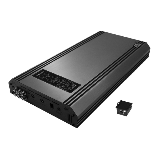
FUNCTIONS & CONTROLS TOP-PANEL 2-Channel Amplifier VE1000.2 / VE1800.2 LINE OUTPUT Provides a full range line level (RCA) output that allows you to trigger additional amplifiers. LINE INPUT This allows you to connect the head unit outputs (CH 1/2 or CH 3/4) by appropriate RCA cables. BALANCED INPUT Accepts a balanced symmetrical line signal from a appropriate Signal Transmitter. - Page 6 FUNCTIONS & CONTROLS TOP-PANEL 2-Channel Amplifier VE1000.2 / VE1800.2 NOTE: If the amplifier's top-panel is white illuminated, the amplifier is in power mode. If the display is red illuminated, the protection mode of the amplifier is activated caused by a malfunction (See page 33) CAUSES: Overheating, short circuit on the speakers, overload (caused by low-impedance or low-power) or damage .
-
Page 7: Functions & Controls
FUNCTIONS & CONTROLS TOP-PANEL 2-Channel Amplifier VE1000.2 / VE1800.2 ACOUSTIC PHASE SHIFT LEFT Allows to adjust the phase modulation (acoustical center) of the left channel between 0 - 180 degrees. ACOUSTIC PHASE SHIFT RIGHT Allows to adjust the phase modulation (acoustical center) of the right channel between 0 - 180 degrees. MONO –... -
Page 8: 2-Channel-Mode: 2 Speakers / Stereo
LOUDSPEAKER WIRING & CONNECTION 2-Channel Amplifier VE1000.2 / VE1800.2 2-CHANNEL-MODE: 2 Speakers / Stereo BALANCED INPUT This Input can optionally be used with LINE OUTPUT appropriate cables and symmetrical signal transmitters. Please do not use Optional triggering to this Input at the same time as the use additional amplifiers. -
Page 9: 1-Channel-Mode: 1 Subwoofer / Mono Bridged
LOUDSPEAKER WIRING & CONNECTION 2-Channel Amplifier VE1000.2 / VE1800.2 1-CHANNEL-MODE: 1 Subwoofer / Mono bridged LEVEL BASS REMOTE MIN - MAX Level Controller White LED = Operation Mode Red LED = Protection Mode BALANCED INPUT This Input can optionally be used with LINE OUTPUT appropriate cables and symmetrical signal transmitters. -
Page 10: 4-Channel Amplifier Ve 600.4 & 1000.4
FUNCTIONS & CONTROLS FRONT-PANEL / REAR-PANEL 4-Channel Amplifer VE800.4 / VE1200.4 LINE OUT Provides a full range line level (RCA) output that allows you to trigger additional amplifiers. LINE INPUT This allows you to connect the head unit outputs (CH 1/2 / CH 3/4) by appropriate RCA cables. BALANCED INPUT CHANNEL 1 &... - Page 11 FUNCTIONS & CONTROLS TOP-PANEL 4-Channel Amplifier VE800.4 / VE1200.4 NOTE: If the amplifier's top-panel is white illuminated, the amplifier is in power mode. If the display is red illuminated, the protection mode of the amplifier is activated caused by a malfunction (See page 33) CAUSES: Overheating, short circuit on the speakers, overload (caused by low-impedance or low-power) or damage .
-
Page 12: Functions & Controls
FUNCTIONS & CONTROLS TOP-PANEL 4-Channel Amplifier VE800.4 / VE1200.4 ACOUSTIC PHASE SHIFT LEFT Adjust the phase modulation (acoustical center) of the Channel 1 between 0 - 180 degrees. ACOUSTIC PHASE SHIFT RIGHT Adjust the phase modulation (acoustical center) of the Channel 2 between 0 - 180 degrees. ON - In this position the phase modulation is activated and can be separatly adjusted with T1 and T2 (See page 32). - Page 13 LOUDSPEAKER WIRING & CONNECTION 4-Channel Amplifier VE800.4 / VE1200.4 4-CHANNEL-MODE: 4 Speakers / Stereo BALANCED INPUT CH 1&2 / CH 3&4 This Input can optionally be used with appropriate cables and symmetrical signal transmitters. Please do not use this Input at the same time as the RCA Inputs.
- Page 14 LOUDSPEAKER WIRING & CONNECTION 4-Channel Amplifier VE800.4 / VE1200.4 3-CHANNEL-MODE: 2 Speakers / Stereo & 1 Subwoofer / Mono bridged BALANCED INPUT CH 1&2 / CH 3&4 This Input can optionally be used with appropriate cables and symmetrical signal transmitters. Please do not use this Input at the same time as the RCA Inputs.
-
Page 15: 2-Channel-Mode: 2 Subwoofer / Mono Bridged
LOUDSPEAKER WIRING & CONNECTION 4-Channel Amplifier VE800.4 / VE1200.4 2-CHANNEL-MODE: 2 Subwoofers / Mono bridged BALANCED INPUT CH 1&2 / CH 3&4 This Input can optionally be used with appropriate cables and symmetrical signal transmitters. Please do not use this Input at the same time as the RCA Inputs. -
Page 16: Special Features
RCA's Balanced wires are insusceptible against interferences. But therefor an signal transmitter with specific wires is required. Ask your specialist dealer for the required equipment. Acoustic Phase Shift The ESX-VISION VE Series Amplifiers have an integrated channel separated Phaseshift Control. By controlling the phase, perfect soundstaging is realisable. Conventionally Systems... -
Page 17: Trouble Shooting
TROUBLE SHOOTING System does not turn on 1. Check all fuses. 2. Check all connections. 3. Measure the +12 volt and remote turn on voltages at the amplifier terminals. If these are non existent or too low, take voltage measurements at fuse holders, distribution blocks, the head unit’s +12 volt and remote leads to localize the problem. - Page 18 NOTES...
- Page 19 NOTES...
Need help?
Do you have a question about the VISION2 Series and is the answer not in the manual?
Questions and answers