
Subscribe to Our Youtube Channel
Related Manuals for Rosenbauer RS14 EFI


Summary of Contents for Rosenbauer RS14 EFI
- Page 1 Operation manual Power Generator RS14 EFI / RS14 EFI Super silent Item number: 319852-003 Release: 12/2018 Language: English Abbreviation: JWin...
-
Page 2: Table Of Contents
5.1 Functional and working principle ....5.2 General description of RS14 EFI power generator ..5.3 Control unit ........ - Page 3 6.2 Preparation for initial operation ..... 6.3 Preparation for startup ......6.3.1 Positioning the power generator .
-
Page 4: Legal Notice
ORIGINAL OPERATION MANUAL Legal notice Copyright All rights to this manual and its attachments lie with Rosenbauer International AG. The documents are only entrusted to the recipient for their personal use. Reproduction, reprinting (electronically or mechanically), translations in other languages or all other duplication, also of parts of the manual, are only allowed with written permission. -
Page 5: Declaration Of Conformity
Declaration of conformity Declaration of conformity RS 14 EFI According to EC Machinery Directive 2006/42/EC, Annex II, part 1A Herewith declares Rosenbauer International AG Fire fighting technology A - 4060 Leonding, Paschinger Str. 90 Address: Postbox 176, 4021 Linz, Austria... -
Page 6: Declaration Of Conformity Rs 14 Super Silent Efi
Declaration of conformity RS 14 SUPER SILENT EFI Declaration of conformity RS 14 SUPER SILENT EFI According to EC Machinery Directive 2006/42/EC, Annex II, part 1A Herewith declares Rosenbauer International AG Fire fighting technology A - 4060 Leonding, Paschinger Str. 90 Address: Postbox 176, 4021 Linz, Austria... -
Page 7: Introduction
If this manual contains a technical error or a typographical error, Rosenbauer reserves the right to make change at any time and without no- tice. This manual may contains figures and descriptions, that are not built into the delivered product. -
Page 8: Identification
Introduction Identification Identification Identifying the serial number is important when referring to the manufactur- er in regards to part and technical issues. The serial number of the power generator is stamped on the type plate. The type plate is on the bottom of the battery box cover, RS 14 EFI power generator: RS 14 SUPER SILENT EFI power generator: ►... -
Page 9: Use Of The Operation Manual
Introduction Use of the operation manual Use of the operation manual 3.4.1 Validity This manual contains information needed for the operation of the product. This manual contains descriptions of special equipment as well as some abstractions and exemplary illustrations. The actual equipping of your prod- uct may therefore differ in part from the descriptions and illustrations. - Page 10 Introduction Use of the operation manual Warning notices The safety information warns the user of risk and informs them how these risks can be avoided. Safety information stands at the beginning of a chapter before handling in- structions from which a dangerous situation can occur. Further safety infor- mation is found at the start of this manual.
-
Page 11: Safety
Improper use of the product can result in personal injury. Additionally, the product or other material assets of value may be damaged. Rosenbauer can warrant the safety, reliability and performance of its prod- uct only if the product is used in accordance with the stipulations in this manual. -
Page 12: Markings And Warning Signs
Safety Markings and warning signs Markings and warning signs Safe use is only possible, if all necessary information for a safety operation are observed. These informations are especially including safety- and warning instructions. In addition to the instructions in this operating manual read and observe all the safety- and warning signs affixed to the product. -
Page 13: Training And Qualifications
Even during operation, make sure that persons without technical knowl- edge never operate the product. Modifications and conversions to the product and its accessories may be performed only with written authorization from Rosenbauer and must be performed by a manufacturer-authorised person. 13 / 81... -
Page 14: General Safety Instructions
Pay attention to the operation and service manual of the engine manufac- turer. If faults cannot be solved or if repairs cannot carried out by special trained personnel, immediately contact Rosenbauer International AG or your near- est Rosenbauer representative. 14 / 81... -
Page 15: List Of Conventional Signs
Safety List of conventional signs List of conventional signs 4.6.1 Meaning of the warning signs Danger from electricity. Impending fire risk. Impending risk of explosion. Risk from oxidising materials. Risk of harmful or irritating materials. Impending risk of explosion. Impending acid burn risk. Impending hearing damage. - Page 16 Safety List of conventional signs Impending crushing risk. Threat of environmental contamination. Threat of shearing. 16 / 81...
-
Page 17: Meaning Of The Prohibitory Signs
Safety List of conventional signs 4.6.2 Meaning of the prohibitory signs Handling fire and naked flames forbidden! Do not touch or reach in! Do not stay in the danger area! 17 / 81... -
Page 18: Meaning Of The Caution Signs
Safety List of conventional signs 4.6.3 Meaning of the caution signs Use hearing protection. Wear a protective helmet. Wear a protective suit. Maintain distance. Special caution. 18 / 81... -
Page 19: Warning Notes
Safety Warning notes Warning notes DANGER! Mortal danger or serious injury from electric shock! Maintenance work on live parts may only be carried out by qualified specialist personnel. Observe the safety distance from voltage-carrying parts at all times. Danger of fatal injury or health hazard due to inhalation of toxic exhaust fumes! Combustion engines working in enclosed areas build toxic exhaust fumes. - Page 20 Safety Warning notes Danger of serious injury and damage due to explosion, fire and chemical burns! When charging vehicle batteries, a highly explosive electrolytic gas mixture (hydrogen and oxygen) is released; it is easily flammable and may release highly acidic battery acid. Wear safety goggles whenever servicing a battery.
- Page 21 Safety Warning notes Danger of crushing and sheering of limbs due to moving or rotating parts! Do not reach into or grasp moving or rotating parts. Observe a safety distance to the danger zone. Use protective equipment. Potentially fatal injuries due to the engine taking in flammable gases! Do not operate the engine in areas with a heavy concentration of ...
- Page 22 Safety Warning notes Safety distance with C/HP-nozzle for fire fighting on low-voltage systems Voltage Extinguishing sys- Extinguishing agent Safety distance up to 1 kV C-nozzle Water spray jet, dry powder, 1 m (3 ft) extinguishing gas C-nozzle Full water jet 5 m (16 ft) HP- nozzle Full water jet...
- Page 23 Safety Warning notes CAUTION! Danger of injury for the operator due to performing action in wrong order! Individual operating instructions must be done in the prescribed order. Danger of hearing damage from standing near the running engine for long periods! Use hearing protection.
- Page 24 Safety Warning notes Environmental and health hazard due to lubrication oils! Lubrication, transmission and hydraulic oils can cause permanent water pollution and endanger fauna and flora of all types. Avoid skin contact with hazardous oils. Avoid ground contact with lubrication oils. ...
- Page 25 Safety Warning notes NOTICE Material damage due to thermal overloading of the portable power generator! It is prohibited to operate the portable power generator with closed roller shutters and hinged steps. If the portable power generator is equipped with an exhaust hose through the compartment, the portable power generator should only be operated in stowed position and with open roller shutters and hinged steps for max.
-
Page 26: Product Description
Product description Functional and working principle Product description Functional and working principle The mobile power generator is approved for the fire department according to DIN 14685-1 and ÖBFV RL ET-01. The power generator consists of a gasoline internal combustion engine with flanged generator in a carrying pan with switch box and control unit as well as a GFRP housing. -
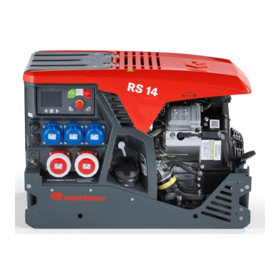
Page 27: General Description Of Rs14 Efi Power Generator
Product description General description of RS14 EFI power generator General description of RS14 EFI power generator 11 12 Potential equalisation connection RS 14 EFI power generator FireCAN connection Carrying frame RLS lighting head connection Carrying strap Remote start / stop connection... -
Page 28: Control Unit
Product description Control unit Control unit Functions and displays on the control unit Power generator control unit Start generator Stop generator ECO Mode (option) External refuelling Emergency stop Ground wire testing device (if available) Scroll forward one screen page Scroll back one screen page Confirm message / selection Pilot lamps display range Operating mode indicators... -
Page 29: Function Switches
Product description Function switches Function switches Symbol Name Functional description The switch activates the control unit after a short keystroke. The power generator Start power gener- is started in the event of a longer key- ator stroke. The switch is backlit for active control unit. -
Page 30: Ground Wire Testing Device
Product description Ground wire testing device Ground wire testing device Symbol Name Functional description Ground wire test- The connection is used to check the ing device (if avail- ground wire connection between the able) power generator and consumer. Warning lights Symbol Name Functional description... - Page 31 Product description Warning lights Symbol Name Functional description Emergency stop pilot lamp indicator when the emergency stop switch was pressed. The pilot lamp has two switch- ing conditions: Emergency stop • Active: emergency stop switch acti- vated • Inactive: Normal operation Fuse monitoring pilot lamp indicates when a fuse has tripped.
-
Page 32: Operating Mode Indicators
Product description Operating mode indicators Operating mode indicators Symbol Name Functional description APC operating condition indicator indi- cates if the power generator is at risk of thermally overheating. An automatic power control is activated and prevents overheating of the generator by reducing the output power at the sockets by grad- Active output con- ually reducing the voltage at the sockets. -
Page 33: Page Navigation
Product description Page navigation Page navigation Symbol Name Functional description The page indicator is only for orientation. Page navigation It indicates the number of pages and highlights the requested page. Main image The main screen shows the most important information at a glance. 100 % Main image Fuel fill level:... - Page 34 Product description Page navigation Detailed view The detail view displays the load distribution per phase, and whether the output voltage is within the permissible range. This view is especially impor- tant in operations. In the event of an overload the location of where the overload took place is displayed at the press of a button and it can react immediately.
- Page 35 Product description Page navigation Service view The service view displays the operating hours indicator and test routine for the ISO self test. 0:3 h ISO TEST 5SEC T:21 F:0.0 SPN:0 FMI:0 E:0 U:12.4 1810.B00349 890532-001 Service view ISO self test routine: By pressing and holding the Start ISO test function switch an ISO error is simulated.
- Page 36 Product description Page navigation Expert view The expert view displays the current status of the attached consumers with even more details. Voltage, power, active power, and cosine phi are broken down for each phase. This makes searching for the source of an error much easier.
-
Page 37: Options
Product description Options Options 5.9.1 Optional equipment Exhaust gas hose DANGER! Inhalation of toxic exhaust fumes can cause death or serious damage to health! During operation of internal combustion engines in confined spaces, toxic gases build up. In order to properly discharge the hot exhaust gases, use the provided, standardized exhaust gas hose. - Page 38 Product description Options Holder for exhaust gas hose Spacer for hot exhaust gas hose in front of sensitive surfaces. Through its use the hot exhaust gas hose is kept away from sensitive sur- faces. Holder for exhaust gas hose 45° exhaust adapter The exhaust adapter serves for lateral deflection of the exhaust gas.
- Page 39 Product description Options Exhaust gas deflector Assembly of the exhaust gas adapter may only be carried out by trained specialist personnel. Take note of general dangers that could occur during assembly. The corresponding liquid-locking compound must be used. When using the power generator on turntable ladders and aerial rescue de- vices the deflector can be used for exhaust gas discharge upwards.
- Page 40 Product description Options Wheel set with pulling device Assembly of the wheel set may only be carried out by trained specialist per- sonnel. Take note of general dangers that could occur during assembly. The power generator can be equipped with a wheel set and a pulling device for manoeuvring and 1-man transport.
- Page 41 Product description Options In addition, a locking bolt can also be purchased. This is used to fix the un- folded carrying handle. The power generator may only be transported with the locking bolt fully inserted. Locking bolts Trolley For transportation, the power generator can be equipped with a trolley. In order to manoeuvre the trolley well, it is equipped with two steerable and brakeable transport castors.
- Page 42 Product description Options Fuel cannister The fuel cannister is to be used for filling the power generator. It has a ca- pacity of 20 litres. The fuel in the portable fuel cannister is to be changed at least twice a year (depletion or replacement), because conditions for stor- age (vibration, high temperature fluctuations) reduce the knock resistance of the fuel.
- Page 43 Product description Options External refuelling set A 1.5m connection line between the fuel canister and the external fuelling connector (7) on the power generator. External refuelling set MAGCODE battery charger MAGCODE battery charger For further information, please refer to the device manufacturer's operation manual.
- Page 44 Product description Options Socket distributor Mobile plastic distributor 2 x 400 V,IP 44. With 3 metre cable HO7RN-F 5G 1.5 mm². Input socket 16 A, 5 p, 400 V. 2 CEE 16 A, 400 V sockets. 400 V socket distributor Tool kit consists of: •...
- Page 45 Product description Options RLS1000 LED lighting system The RLS1000 light head can be attached to the power generator by means of optional adapters, this requires at least two extensions. To ensure operational safety, the RLS1000 can be turned on only when the engine is running and the battery voltage >...
- Page 46 Product description Options Retaining plate assembly Retaining plate teeth direction Retaining plate teeth direction Rear wall plate teeth direction on power generator ► Insert the lighting head into the adapter support with the extensions and cable into RLS light head connection. The extensions can be individually locked by twisting, to prevent ...
-
Page 47: Functional Options
Product description Options 5.9.2 Functional options ECO mode (speed reduction) The speed reduction is automatically activated as soon as the power gen- erator is started. The reduction depends on the engine temperature and takes place after approx. 20 seconds when the engine is running warm, if no consumers are connected. - Page 48 Product description Options Insulation monitoring The RS14 EFI / Super Silent power generator has insulation monitoring. Depending on the variant this is designed as non shut down or shut down . CAUTION! Insulation monitoring If an insulation fault occurs at the power generator or at a consumer ...
- Page 49 Product description Options Insulation monitoring "not shutting down" An insulation fault is indicated by a warning (optical and acoustic) on the generator. Depending on the option selected the power generator is shut down or not. For technical reasons, the network is not disconnected from the sockets.
- Page 50 Product description Options sockets and the two 400 V CEE socket on the front are physically separated from the generator. The ISO monitor is deactivated. With system supply no electrical consumers may be connected to the front sockets. Position 0 changeover position All outer conductors and all neutral conductors are physically separated from the generator.
-
Page 51: Operation
Operation Transporting the power generator Operation Transporting the power generator CAUTION! Risk of injury to operating personnel during transport The power generator may only be transported with the carrying handle provided for the purpose. Unfolded carrying handles represent a trip hazard! Fold the carrying handles back in after use. -
Page 52: Preparation For Initial Operation
Operation Preparation for initial operation Additional operators are needed for slopes and downhill gradients. Preparation for initial operation The sequence of the described processes is to be maintained without ex- ception! Before initial start-up, check the correct fluid level of all consumables. ►... -
Page 53: Preparation For Startup
Operation Preparation for startup Preparation for startup The sequence of the described processes is to be maintained without ex- ception! Before each start-up it should be checked that all operating materials (oil etc.) are full. ► Carry out complete visual checks. ►... -
Page 54: Monitoring During Operation
Operation Monitoring during operation Monitoring during operation The operating elements must always be within reach of the operator. Continuous monitoring of: • Warn devices on the control unit. • fuel capacity, oil pressure, etc. If power generator poses a risk to personnel, disconnect the concerned consumer immediately, or switch off the power generator. - Page 55 Operation Warning notes Danger of explosion due to flammable fuel! During work on the fuel system, fuel can ignite and cause potentially fatal injuries. Do not smoke. Keep fuel away from open flame. When handling fuel, always keep a fire extinguisher at hand. ...
-
Page 56: Start Power Generator
Operation Start power generator Start power generator Do not start the power generator with consumers connected. Starting via electrical starting device ► Briefly actuate Start generator function switch to switch on the ignition. The control unit is activated - display illuminates. ... -
Page 57: Check Ground Wire (If Available)
Operation Check ground wire (if available) Check ground wire (if available) DANGER! Mortal danger or serious injury from electric shock! Observe the safety distance from voltage-carrying parts at all times. Only use consumers in flawless technical condition. Do not earth power generator. ... -
Page 58: Connect Consumer
Operation Connect consumer Connect consumer DANGER! Mortal danger or serious injury from electric shock! Observe the safety distance from voltage-carrying parts at all times. Only use consumers in flawless technical condition. Do not earth power generator. Do not connect the ground wire to an existing equipotential bonding ... -
Page 59: Shut Down Power Generator
Operation Shut down power generator Shut down power generator Disconnect consumer ► Switch off consumer and pull the plug out of the socket. ► Close the socket covers. Operate the power generator for approx. 2 mins without load. Shut down power generator CAUTION! Burning hazard from touching the hot engine or engine attachments! Do not remain in the danger area. -
Page 60: 6.10 Fuelling And Refuelling
Operation Fuelling and refuelling: 6.10 Fuelling and refuelling: To perform a safe refuelling operation, it is essential to comply with all se- curity measures. WARNING! Risk of fire and explosion! The power generator may only be refueled during operation with the ... -
Page 61: Fuelling Process
Operation Fuelling and refuelling: Limited shelf life of fuel The fuel in the tank of the power generator must be utilised within six months. Otherwise deposits (sediments and precipitates) can occur. The fuel in the fuel canister is to be changed at least twice a year ... - Page 62 Operation Fuelling and refuelling: After refuelling ► Store fuel canister at a safe distance from the power generator. Refuelling with external refuelling set Installation of the external refuelling set may only be carried out with the engine switched off. ►...
-
Page 63: Servicing And Cleaning
Servicing and cleaning Service plan Servicing and cleaning Service plan 7.1.1 Maintenance according to the manufacturers operation manual Observe the operating and maintenance manual of the engine manufactur- 63 / 81... -
Page 64: Inspection Procedures
The generator must be subjected to a recurrent testing in accordance with the relevant national regulations. Observe the applicable laws and regula- tions. Rosenbauer recommends that a recurring test be carried out every 5 years at the latest. The recurring tests are to be documented accordingly. - Page 65 Servicing and cleaning Inspection procedures Hose lines All hose lines, especially fuel lines, are to be checked at least once a year for obvious defects in the course of a visual check. The following special cri- teria are to be observed while doing so: ►...
-
Page 66: Service Procedures
Only technology which is regularly maintained by specialists can meet the high demands. Rosenbauer service partners will gladly provide you with comprehensive advice about inspections and Service PLUS, as well as about the exact scope and costs of testing and maintenance work. - Page 67 Servicing and cleaning Service procedures Preparatory activities for changing RS14 EFI Super Silent oil filter To change the oil filter on the propulsion engine of the power generator, it is necessary to remove a ventilation plate beforehand. ► The oil filter is located behind the lateral ventilation plate next to the fuel tank cap.
- Page 68 Servicing and cleaning Service procedures RS14 EFI Super Silent design variant: ► The air filter set is located under the top cover of the power generator. To remove the cover the rubber tensioner on the side of the engine must be released.
- Page 69 Servicing and cleaning Service procedures Replace starter battery ► Open battery compartment cover and release the battery fastening strap. ► Disconnect battery terminal In avoid sparks first disconnect the cable from the earth terminal and then from the positive terminal. ►...
- Page 70 Servicing and cleaning Service procedures Fuse strip The fuse strip is located below the battery compartment cover. If an over- load occurs due to a consumer, the circuit breaker is activated. An addition- al message is output on the control unit. The circuit breakers may only be replaced by trained specialist personnel.
-
Page 71: Troubleshooting
Troubleshooting Service procedures Troubleshooting Error messages The error messages must consciously be acknowledged with the Confirm message / selectionfunction switch on the control unit in order to switch off the acoustics or to hide the pop-up warning message. Tank sensor ►... - Page 72 Troubleshooting Service procedures Battery charge level ► Battery voltage too low, battery charging via the generator does not work. ► Charging voltage too low, check the generator and the charge regula- tor. Engine temperature ► Too high an engine temperature is shown. Swivel the power generator out, if the power generator is already ...
- Page 73 Troubleshooting Service procedures Low tank fill level ► Remaining tank contents less than 25%. Refuelling required, or switch to external refuelling. Ground wire test ► Successfully performed ground wire test. The tested consumer can be used. 73 / 81...
-
Page 74: Power Generator
Troubleshooting Power generator Power generator Fault Cause Remedy Engine does not start with wet spark plugs Check: (Starter rotates) Air filter Temperature sensor Ignition Water in fuel system With dry spark plus Check Fuel filter Tank capacity Fuel pump Injection valve Throttle valve Spark plugs dirty Clean the spark plug contacts or replace... - Page 75 Troubleshooting Power generator Fault Cause Remedy Engine does not start Battery is not connected. Connect battery and check contacts (engine does not Battery empty Charge or replace battery (votmeter) crank) Emergency stop pressed Rotate the switch clockwise, to deactivate the emergency stop No power supply to the con- Check power supply and ground on the trol unit...
-
Page 76: Disposal
Disposal Power generator Disposal Dispose of all materials and old parts that are produced through the han- dling and repair of this unit in an environmentally-friendly way. Disposal of used oil, cooling water and fuels Used oil, cooling water and fuels are water-polluting substances. Ensure the correct disposal of used oils and fuel. -
Page 77: Technical Data
Mobile power generating unit In particular fire departments or users who re- quire a higher level of protection Manufacturer Rosenbauer International AG RS 14 EFI (A0515) Type designation RS 14 EFI SUPER SILENT (A0516) ÖBFV-RL ET-01 / 8 kVA power generator with... - Page 78 Technical data Power generator Generator Protective separation with several consumers Protective measures and equipotential bonding Number of poles / 2 / 3,000 rpm Speed Distortion factor < 5% Size BG 132 a. country-specific special design: 130 / 225 V b. country-specific special design: 60 V c.
-
Page 79: List Of Spare Parts
11.1 List of spare parts Access to the online spare parts catalogue for the power generator is pro- vided under the following link. https://spareparts.rosenbauer.com/template/index.php User name: A051 Password: A051 When logging in make sure you watch out for capital and lower case letters. -
Page 80: List Of Abbreviations
List of abbreviations List of abbreviations Fire fighting specific abbreviations Power take off Normal pressure High pressure AFFF Aqueous film forming foam Piston priming pump, priming pump Aluminium technology O-stream nozzle Portable pump UHPS Ultra high pressure system Plastics and drinking water DVGW German Association of Gas &... - Page 81 List of abbreviations General abbreviations lbs/s Pounds per second Feet Gallons per minute 81 / 81...
Need help?
Do you have a question about the RS14 EFI and is the answer not in the manual?
Questions and answers