Table of Contents
Advertisement
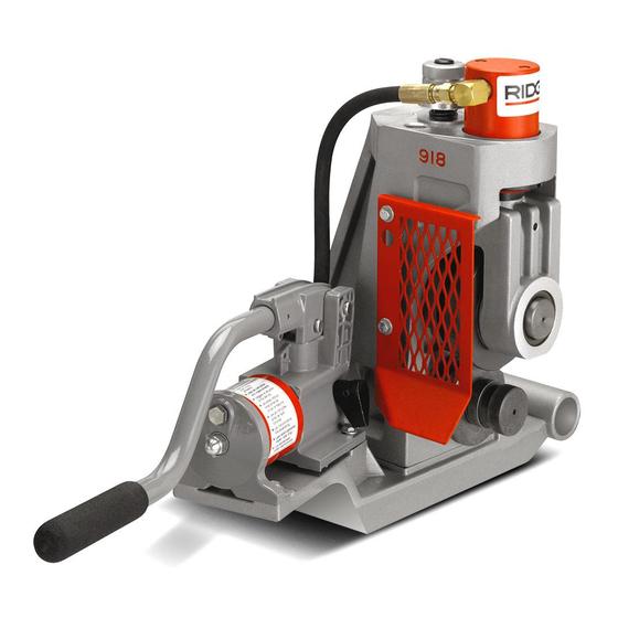
918
OPERATOR'S
MANUAL
WARNING!
Read this Operator's Manual
carefully before using this
tool. Failure to understand
and follow the contents of
this manual may result in
electrical shock, fire and/or
serious personal injury.
Roll Groover
99 Washington Street
Melrose, MA 02176
Phone 781-665-1400
Toll Free 1-800-517-8431
Visit us at www.TestEquipmentDepot.com
Advertisement
Table of Contents

Related Manuals for RIDGID 918


Summary of Contents for RIDGID 918
- Page 1 Roll Groover OPERATOR’S MANUAL WARNING! Read this Operator’s Manual carefully before using this tool. Failure to understand and follow the contents of 99 Washington Street this manual may result in Melrose, MA 02176 electrical shock, fire and/or Phone 781-665-1400 serious personal injury. Toll Free 1-800-517-8431 Visit us at www.TestEquipmentDepot.com...
-
Page 2: General Safety Information
918 Roll Groover General Safety Information • When operating a tool outside, use an outdoor extension cord marked “W-A” or “W”. These cords WARNING! Read and understand all instructions. Failure are rated for outdoor use and reduce the risk of elec- to follow all instructions listed below may trical shock. -
Page 3: Specific Safety Information
918 Roll Groover Tool Use and Care around your arm or other body parts with enough force to crush or break bones. • Do not use tool if switch does not turn it ON or OFF. Any tool that cannot be controlled with the switch Roll Groover Safety is dangerous and must be repaired. -
Page 4: Description, Specifications And Standard Equipment
The 918 Roll Groover includes two (2) groove and drive shaft sets that can groove the following pipe: • 918 Groover with 2″ – 6″ drive shaft and groove set • 2″ – 6″ Schedule 10 and 40 • 8″ – 12″ Drive shaft and groove set •... - Page 5 ″ x ″ Bolts (4) Figure 2 – Installing on 300 Power Drive Figure 3 – 918 Heavy Duty Roll Groover on 1822 Mounting 1. Remove carriage or other attachments from the 300 Base Power Drive. Installing on 1822 Threading Machine with 1406 2.
- Page 6 Position reamer inside the die head to CAUTION prevent accidental contact. 2. Place 918-4 on the far side carriage rail and lower onto near side rail. (Figure 6) 3. Position base so that the drive bar feeds into the open chuck.
- Page 7 Position reamer inside the die head to CAUTION pre vent accidental contact. 2. Place 918-5 on far side of carriage rail, lower onto front rail and tighten front chuck (Figure 8). 3. Position base so that drive bar feeds into open chuck.
-
Page 8: Machine Inspection
918 Roll Groover 11. Inspect the groove rolls to insure they are not dam- Machine Inspection aged or worn. Worn groover rolls can lead to pipe slippage and poor quality grooves. WARNING Machine and Work Area Set-Up WARNING Do not use this Roll Groover with a power drive or threading machine that does not have a foot switch. - Page 9 918 Roll Groover To avoid electrical shock and electrical fires, Operating the 918 Roll Groover WARNING never use an extension cord that is damaged or does not meet the following requirements. WARNING • The cord has a three-prong plug similar to shown in Electrical Safety section.
- Page 10 RETURN position (away from operator). (Figure 9) 3. Square pipe and pipe support to roll groover making sure pipe is flush against drive roll flange. (Figure 10) Figure 11 – Leveling Pipe on Pipe Support and 918 Mount Setting Degree ° toward operator °...
- Page 11 8″ schedule 40 steel pipe harder than 150 BHN. 1. Flip the directional switch from OFF and step on power drive or threading machine foot switch while ap- plying downward pressure on the 918 pump handle. Allow one full pipe rotation between quarter strokes of the pump handle.
- Page 12 Removing and Installing Roll Sets with Solid Drive Shafts (2″ – 6″, 8″ – 12″) 1. Recommend removing 918 Roll Groover from power drive or machine, and placing it on a work bench in an upright position. If a suitable workplace is not available, Figure 19 –...
- Page 13 ″, 2″ – 6″ Copper) (1″, 1 • Release pressure on the spindle lock pin, allowing 1. Recommend removing 918 Roll Groover from power to retract. drive or machine, and placing it on workbench in an 5. Installing Groove Roll: upright position.
- Page 14 NOTE! Once the stabilizer is adjusted for a selected tighten the draw bolt. pipe diameter, it does not have to be readjusted. • Release pressure on the spindle lock pin, allowing 1. Place pipe on to drive roll on Model 918 Roll Groover. to retract. Ridge Tool Company...
- Page 15 Only the following RIDGID products have 3. Engage hydraulic pump and bring groove roll (upper been designed to function with the 918 Roll Groover. Other accessories suitable for use with other tools may be- roll) down until it contacts the pipe.
- Page 16 918 Roll Groover Table I. Standard Roll Groove Specifications NOTE! All Dimensions are in Inches. NOM. PIPE MIN. GASKET GROOVE GROOVE NOM. PIPE DIAMETER WALL SEAT WIDTH DIAMETER GROOVE SIZE O.D. TOL. THK. +.015/-.030 +.030/-.015 O.D. TOL. DEPTH (Ref. #2) 1.315...
- Page 17 918 Roll Groover Table III. Troubleshooting PROBLEM CAUSE CORRECTION Incorrect size of grooving and driving rolls. Install correct size of grooving and driving rolls. Rolled groove too narrow or too wide. Mismatched grooving and driving rolls. Match grooving and driving rolls.
- Page 18 918 Roll Groover Table III. Troubleshooting (cont.) PROBLEM CAUSE CORRECTION Pipe raises or tends to tip Not level. Adjust stands to level pipe. groover over backwards. Pump not delivering oil, Pump release valve open. Close release valve. cylinder does not Low oil in reservoir.
-
Page 19: Maintenance Instructions
Service and repair work on this Roll Groover must be per- formed by qualified repair personnel. Machine should be taken to a RIDGID Independent Authorized Service Center or returned to the factory. All repairs made by Ridge service facilities are warranted against defects in material and workmanship. - Page 20 99 Washington Street Melrose, MA 02176 Phone 781-665-1400 Toll Free 1-800-517-8431 Visit us at www.TestEquipmentDepot.com Printed in U.S.A. 12/12 999-998-946.10 EC39404 REV. B...
Need help?
Do you have a question about the 918 and is the answer not in the manual?
Questions and answers