Advertisement
Quick Links
Linear drive
DFPI-...-ND2P-C1V-NB3P-A
(en) Operating instructions
Original: de
Linear drive DFPI-...-ND2P-C1V-NB3P-...
1
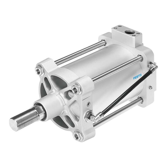
Configuration
aB
aA
aJ
5
9
1
Housing
2
Electrical and pneumatic connec
tion (under the protective cap)
3
End cap
4
Bearing cap
5
Mounting interface in accordance
with ISO 15552
6
Air duct
Fig. 1
The DFPI-...-ND2P-C1V-NB3P- is an electropneumatic linear drive consisting of:
– a double-acting pneumatic cylinder with
– integrated displacement encoder (potentiometer) for determining the actual
position
– integrated valve block with directional control valves for controlling the piston rod
– integrated positioner for position control.
Proximity sensors can be screwed onto the tie rods if necessary for additional bin
ary sensing of positions.
A pressure compensation element prevents the formation of condensate inside the
housing in the event of temperature fluctuations, thus protecting the internal elec
tronics.
Festo AG & Co. KG
Postfach
73726 Esslingen
Germany
+49 711 347-0
www.festo.com
8062742
1608
[8062744]
. . . . . . . . . . . . . . . . . . . . . . . . . . .
7
Pressure compensation element
8
Earth terminal
9
Flow control screw
aJ
Piston rod with mounting thread
for accessories
aA
Spanner flat
aB
Tie rod
For DFPI-...-ND2P-C1V-NB3P-... the electrical and pneumatic connections are pro
tected against external mechanical influences by a rugged flange receptacle.
The compressed air supplied from one side is fed via an unprotected line parallel
to the cylinder barrel. Tie rod screws are used to attach the cylinder end cap.
Accessories è www.festo.com/catalogue.
Feature
Type
Piston diameter
Stroke
Function
Cushioning
Displacement en
coder
Method of measure
ment
Regulation
Directional control
valve
Standard
Connection type
Safety position
English
Feedback
Fig. 2
Type code (e.g. DFPI-100-200-ND2P-C1V-NB3P-A)
1
2
Safety
Intended use
2
The DFPI-...-ND2P-C1V-NB3P-... linear drive is intended for regulation in process
engineering systems. It is particularly appropriate for pneumatic positioning under
rough operating conditions.
3
• Only use the product in its original status, without any unauthorised modifications.
• Only use the product if it is in perfect technical condition.
• Use only proximity sensors approved for the product.
• Take into consideration the ambient conditions at the location of use.
• Observe the specifications on the product labelling.
• Comply with all applicable national and international regulations.
Operating medium
4
• Only use compressed air in accordance with the specifications (è Chapter 11).
• Only use unlubricated compressed air under normal conditions. Once the
5
product has been used with lubricated compressed air, it must continue to be
operated with compressed air only.
Drive
Impermissible lateral forces on the piston rod can damage the rod bearing or the
linear drive.
• Do not exceed the maximum permissible lateral forces on the piston rod
(è Fig. 11).
• Guide the piston rod, if necessary, to avoid start-up oscillations.
Return to Festo
6
Hazardous substances can endanger the health and safety of personnel and cause
damage to the environment. To prevent hazards, the product should only be re
turned upon explicit request by Festo.
7
• Consult your regional Festo contact.
• Complete the declaration of contamination and attach it to the outside of the
packaging.
• Comply with all legal requirements for handling hazardous substances and
8
transporting dangerous goods.
3
Function
The compressed air applied at connection P
is directed by the integrated valve block al
ternately to the two piston chambers of the
cylinder – depending on the setpoint posi
tion that is specified. This causes the piston
rod connected to the piston to move
backwards and forwards.
The maximum possible venting of the two cylinder chambers can be set independ
ently of each other using flow control screws D2 and D4. D2 controls the venting
flow when the piston rod advances. D4 controls the venting flow when the piston
rod retracts. This can be used to control the maximum travel speed of the linear
drive in the range from 0 %...100 %. In the factory setting, the flow control screws
are completely open.
Positions are specified via an analogue setpoint signal (4...20 mA). The piston rod
is positioned in a controlled manner.
The integrated positioner performs position control of the piston rod within the
available stroke range.
Type code
Description
DFPI
Regulated drive for process automation
100, 125, 160, 200,
Specifications in [mm]
250, 320
...
Stroke length freely selectable in the range from
40 to 990; specifications in [mm]
Not specified
Double-acting
N
No cushioning
D2
Analogue
P
Potentiometer
C1
Controller 1
V
Integrated
NB3
Based on ISO 155522
P
Protected pneumatic connections
Not specified
Piston rod advancing
R
Piston rod retracting
A
Analogue feedback
Fig. 3
Advertisement

Related Manuals for Festo DFPI-...D2P-C1V-NB3P series


Summary of Contents for Festo DFPI-...D2P-C1V-NB3P series
- Page 1 Hazardous substances can endanger the health and safety of personnel and cause damage to the environment. To prevent hazards, the product should only be re turned upon explicit request by Festo. • Consult your regional Festo contact. • Complete the declaration of contamination and attach it to the outside of the packaging.
- Page 2 5-pin plug connector. • When shipping used products: Comply with all legal requirements for handling Allocation Connection hazardous substances and transporting dangerous goods. For return to Festo è Chapter 2. Power supply 24 V DC • Remove all attachments.
- Page 3 1. Prepare pneumatic connection. After successful initialization the linear drive is ready for operation. – Use O.D. pneumatic lines (e.g. plastic tubing PUN-8x1,25 from Festo): Supply air (P) 8 mm; exhaust air (R) 10 mm. Note – Cut tubing ends at right angles and without burrs. This avoids damage to The initialisation procedure may take several minutes depending on the size of internal O-rings.
- Page 4 Min./max. stroke allowance [mm] 0…4 Repair Design Piston rod, cylinder barrel • Repairs to the product are only permissible by Festo's repair service. Cushioning No cushioning Fault clearance Assembly position Mode of operation Double-acting...
Need help?
Do you have a question about the DFPI-...D2P-C1V-NB3P series and is the answer not in the manual?
Questions and answers