Advertisement
Advertisement
Table of Contents

Subscribe to Our Youtube Channel
Related Manuals for pitsco Blinky


Summary of Contents for pitsco Blinky
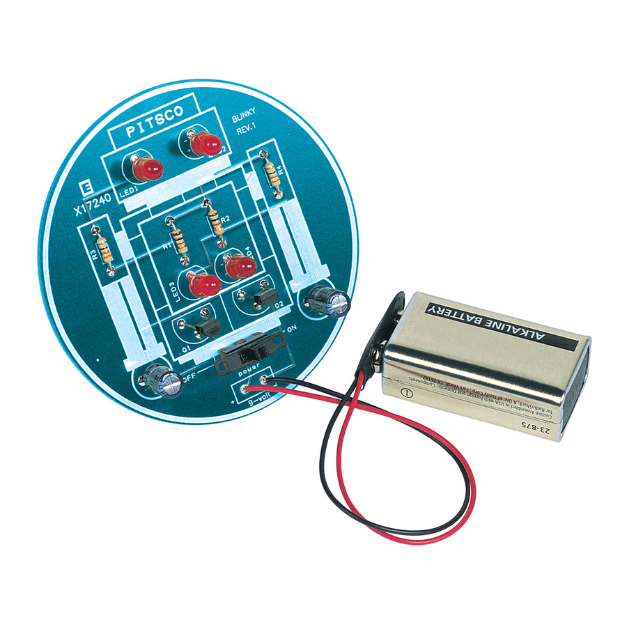
- Page 2 Be sure to read and follow all directions. Using the Included Materials section, make sure you have all of the Blinky parts. The letters next to the Part Name correspond to the part’s image (Figure 1). Notice the location(s) of each part on the circuit board are to the left of the part names.
- Page 3 Turn over the circuit board (facedown) and solder the two ends of the battery snap wires using the following soldering technique. Heat BLINKY the end of the battery snap wire and the trace REV.1 by holding the tip of the soldering iron against both the trace and the wire.
- Page 4 12. Locate the two 10kΩ resistors (these have brown, black, and orange stripes) and insert them in the R1 and R2 locations. Solder in place and clip excess leads. 13. Locate the two transistors and insert them in the Q1 and Q2 locations. Place the transistor so the flat side faces the top of the board (toward the robot’s head) before soldering.
Need help?
Do you have a question about the Blinky and is the answer not in the manual?
Questions and answers