Table of Contents
Advertisement
Quick Links
BENCH-TOP DIGITAL MULTIMETER
INSTRUCTION MANUAL
SK-4033 / SK-4035
Thank you for purchasing KAISE MODEL
SK-4033/4035 BENCH-TOP DIGITAL
MULTIMETERS. To obtain the maximum
performance of this instrument, read this
Instruction Manual carefully, and take
safe measurement.
Features
■Comparator Function
Useful for the quality check in the
production line. Comparator relay output is
also possible by using the output terminal.
■Output Terminal
Connecting to the external inspection
equipment is possible by using the
equipped photoMOS relay output terminal.
■True RMS
SK-4035 assures the accurate measurement
by True RMS.
422 Hayashinogo, Ueda City, Nagano Pref.,
386-0156 Japan
TEL : +81-268-35-1601 / FAX : +81-268-35-1603
E-mail : sales@kaise.com
http://www.kaise.com
CONTENTS
1
1
2
2
3
4
4
6
6
7
9
9
11
12
13
14
14
15
15
16
17
17
18
18
Advertisement
Table of Contents

Subscribe to Our Youtube Channel
Related Manuals for Kaise SK-4033

Summary of Contents for Kaise SK-4033
-
Page 1: Table Of Contents
BENCH-TOP DIGITAL MULTIMETER INSTRUCTION MANUAL SK-4033 / SK-4035 Thank you for purchasing KAISE MODEL CONTENTS SK-4033/4035 BENCH-TOP DIGITAL FOR SAFETY MEASUREMENTS MULTIMETERS. To obtain the maximum 1. UNPACKING AND INSPECTIONS performance of this instrument, read this 2. SPECIFICATIONS Instruction Manual carefully, and take 2-1. -
Page 2: For Safety Measurements
FOR SAFETY MEASUREMENTS To prevent an electrical shock hazard to the operator and/or damage to the instruments, read this instruction manual carefully before using the Insulation Tester. WARNINGS with the symbol on the Insulation Tester and this instruction manual are highly important. The symbol listed in IEC 61010-1 and ISO 3864 means "Caution (refer to instruction manual)". -
Page 3: Specifications
2. OPERATING PRINCIPLE : Σ⊿ Conversion 3. AC MEASUREMENT : SK-4033 : Average rectification, SK-4035 : True RMS (AC coupling) 4. RANGE SELECTION : Auto range / manual range 5. FUNCTION SELECTION : Manual (key operation) 6. POLARITY: Auto ("−" symbol is shown in minus) 7. -
Page 4: Measurement Specifications
1000V AC rms 400.0V ≒10MΩ 100mV for 1 minute 600V Range selection : auto range / manual range 2. AC Voltage (AC. V) SK-4033 : Average rectification / SK-4035 : True RMS Range Resolution Accuracy Input resistance Maximum input Overload protection >100MΩ... -
Page 5: Safety Precautions
4. AC Current (AC. A) SK-4033 : Average rectification / SK-4035 : True RMS Range Accuracy Maximum input Overload protection Resolution Voltage drop Range selection 400.0μA <0.05V 0.1μA 400μA AC rms 4.000mA <0.25V 1μA 0.5A/250V fuse (input terminal) ±1.5%rdg±6dgt Manual 3A/600V fuse (circuit) <0.1V... - Page 6 WARNING 3. Warning for High Voltage Measurement Even for Low Power Circuits of electric/electronic appliances, such as heating elements, small motors, line cords and plugs, High Voltage Measurements are very dangerous. To avoid electric shock hazard, pay careful attention not to touch any part of the circuit. WARNING 4.
-
Page 7: Ac Adapter
WARNING 6. Correct Function Settings Always confirm that the correct measurement function is selected. Do not measure any voltage except in the Voltage (V) function. WARNING 7. Maximum Input Observance Do not measure any elements that might exceed the specified maximum input values of each measurement ranges. -
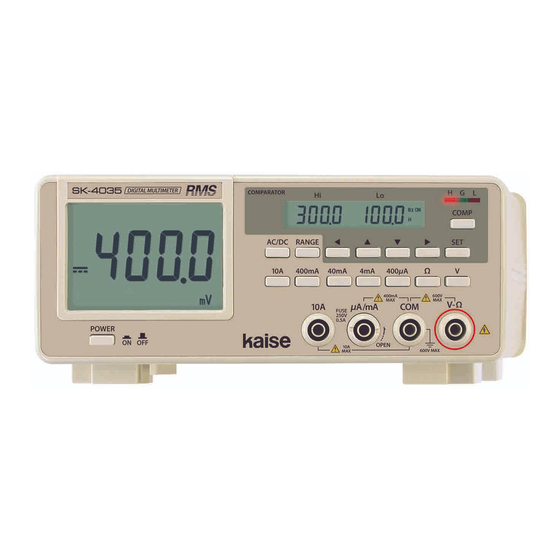
Page 8: Name Illustration
4. NAME ILLUSTRATION FRONT PANEL Main LCD AC/DC Key RANGE Key Comparator LCD Comparator LED COMP Key SET Key △▽ Key Fig. 3 Power Switch Input Terminals Function Keys ※Illustration shows SK-4035 REAR PANEL Comparator Output Terminals AC Adapter Jack Fig. - Page 9 4-2. Measurement Key Switches 1. Power Switch Press this switch to turn ON the instrument. Press it again to turn OFF. 2. AC/DC Key The key to change DC ⇔ AC during voltage and current measurements. Default setting is DC. 3.
-
Page 10: Measurement Procedures
AC Adapter Specification Caution for the Polarity Input : 100V to 240V AC, 50/60Hz The polarity of AC adapter for SK-4033/4035 is Output : 9V DC "Center Plus". Be careful about this when using the ※Switching type commercially available AC adapter. - Page 11 5. Symbol Mark The following symbol marks shown on the instrument and instruction manual are listed in IEC- 61010-1 and ISO 3864. Warning and caution showing that the user should refer to instruction manual Alternating Current (AC) Double Insulation memo - 10 -...
-
Page 12: Voltage Measurement
5-2. Voltage Measurement ( V・∼V ) WARNING ●Do not measure high power line or high power circuit. ●Do not measure any voltage that might exceed the specified maximum input value. ●Before starting the measurement, check the voltage function is selected. ●Detach test leads from the measuring circuit when changing the measurement function. -
Page 13: Resistance Measurement
5-3. Resistance Measurement ( Ω ) WARNING ●Before starting the measurement, check the Ω function is selected. ●Do not measure any voltage in resistance measurement function to avoid electric shock hazard and serious damage to the instrument. ●Detach test leads from the measuring circuit when changing the measurement function. ●When measuring in-circuit resistance, turn off power to the circuit being measured and discharge the all capacitors. -
Page 14: Current Measurement
5-4. Current Measurement ( A・∼A ) WARNING ●Do not measure high power line or high power circuit. ●Do not measure any current that might exceed the specified maximum input value. ●Before starting the measurement, check the correct current function is selected. ●Do not measure any voltage in current measurement function to avoid electric shock hazard and serious damage to the instrument. -
Page 15: Comparator Function
The function useful to check GOOD/FAIL test result under the certain threshold. You can check the result by buzzer and LED in accordance with the preset higher and lower limit. SK-4033/4035 is also capable of comparator relay output by using the solderless terminal. All light up 6-1. -
Page 16: Buzzer Settings
6-2. Buzzer Settings Press for 2 sec. Buzzer timing can be selected as needed. ↓ Buzzer setting mode Enter buzzer setting mode by pressing COMP ON/OFF Key for 2 seconds or more. Press COMP Key and select buzzer timing from ①Buzzer sounds when "G"... -
Page 17: Comparator Relay Output
Important Note for Comparator Measurement ●When taking the comparator measurement with the input terminals are opened, such as when the resistance measurement, comparator always shows "Hi" result with "OL" sign on LCD. To prevent this problem, add GO/STOP signal to your inspection system in reference to the circuit diagram shown in Fig. -
Page 18: Maintenance
7. MAINTENANCE 7-1. Fuse Replacement WARNING ●To avoid electrical shock hazard, finish the measurement when to replace the fuse. ●Detach test leads from measuring circuit and input terminals and disconnect AC Adapter from power source. ●Always use the specified fuse. Do not use this instrument shorting fuse holder or without using the fuse. -
Page 19: Periodical Check And Calibration
WARRANTY SK-4033/4035 is warranted in its entirety against any defects of material or workmanship under normal use and service within a period of one year from the date of purchase of the original purchaser. Warranty service is available at KAISE AUTHORIZED SERVICE AGENCY through your local dealer. - Page 20 KAISE AUTHORIZED DEALER 422 Hayashinogo, Ueda City, Nagano Pref., 386-0156 Japan TEL : +81-268-35-1601 / FAX : +81-268-35-1603 E-mail : sales@kaise.com http://www.kaise.com Product specifications and appearance are subject to change without notice due to continual improvements. 70-1201-4033-1 1003...
Need help?
Do you have a question about the SK-4033 and is the answer not in the manual?
Questions and answers