Advertisement
Quick Links
Functional Test Data
The sounder is controlled by the control panel using the output bits in the communication
protocol.
Protocol bit use:
Output Bit
Function
2
group mode
1 = off
0 = on
1
pulsed mode
1 = on
0 = off
0
continuous mode
1 = on
0 = off
Fault Finding
Problem
Possible Cause
No response or missing
Incorrect address setting
Incorrect loop wiring (polarity reversed)
Too many sounders between isolators
Analogue value 4
Incorrect group address or address setting
Analogue value 1
Sounder test failed
Sounder fails to operate
Control panel has incorrect cause and effect
programming
Incorrect group address setting
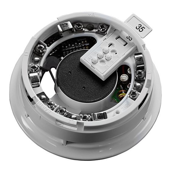
Remote LED
+R
Address & tone
–R
setting
Group address
setting
Volume control
L1
L2
EARTH
–
+
© Apollo Fire Detectors Limited 2004/JDR/JLC
Fig. 2 Integrated Base Sounder wiring
© Copyright Apollo Fire Detectors Limited 2004
Apollo Fire Detectors Limited, 36 Brookside Road, Havant, Hants, PO9 1JR, UK
Tel +44 (0)23 9249 2412 Fax +44 (0)23 9249 2754
Email: techsales@apollo-fi re.co.uk Website: www.apollo-fi re.co.uk
39214-210/Issue 3
Input Bit
Function
2
group mode confi rmed
1 = group
0 = individual
1
pulsed mode confi rmed
1 = on
0 = off
0
continuous mode confi rmed
1 = on
0 = off
Remote LED
+R
Address & tone
–R
setting
Group address
setting
L2
L2
L1 IN
L1 OUT
+
–
–
EARTH
+
Position of Isolator LED
© Apollo Fire Detectors Limited 2004–2005/JDR/JLC/JDR
Fig. 3 Integrated Base Sounder with isolator
wiring
4
General
This guide describes the installation of the following sounders
Part number
Product Description
45681-278
Integrated Base Sounder
45681-277
Integrated Base Sounder & Isolator
45681-291
Slow Whoop version to Dutch Standard NEN2575
45681-290
Slow Whoop version to Dutch Standard NEN2575 & Isolator
45681-292
White Cap only
45681-293
Red Cap only
Connect the sounders only to control panels using either the XP95 or the Discovery protocol.
Note: The Integrated Base Sounder is not suitable for outdoor use.
Mounting Instructions
The sounders may be secured to a UK standard conduit box or surface mounted (providing
there is access through the surface for cabling). If a detector is fi tted, lock it if required by
screwing in the grub screw on the head with a 1.5mm hex driver (part no 29600-095)
Wiring Details
Note: The sounders are polarity sensitive (supply reversal protected) and will not function if
wired incorrectly.
Standard Sounder
Connect the positive and negative loop cables to the L2 and L1 terminals respectively, observ-
Volume control
ing polarity. The wiring terminals accept solid or stranded cables up to 2.5mm². Functional
earth or screen cables may be terminated to the EARTH connection. See Fig. 2.
+
Sounder with Isolator
–
Connect the positive XP95/Discovery loop cables to the L2 terminals, the negative loop in to L1
IN and negative loop out to L1 OUT. (See Fig. 3.) When using the sounder as a stand-alone unit,
a cap is available (red cap part no 45681-293 or white cap part no 45681-292) and is secured
with a 1.5mm, AF hexagon socket head screw. A hexagonal driver (part no 29600-095) is avail-
able from Apollo. The isolator LED can be seen through the moulding as shown in Fig 3.
Address Setting
The address of the sounder is set using seven segments of the eight-segment DIL switch. The
eighth seg ment is used to adjust the volume output. Segments 1-7 of the switch are set to "0"
(ON) or "1", using a small screwdriver or similar tool. A complete list of address settings is shown
overleaf. If a detector is to be fi tted, set the address as described on page 3.
FIRE DETECTORS LIMITED
Integrated Base Sounder
Installation Guide
1
Advertisement

Related Manuals for Apollo 45681-278


Summary of Contents for Apollo 45681-278
- Page 1 1.5mm, AF hexagon socket head screw. A hexagonal driver (part no 29600-095) is avail- wiring able from Apollo. The isolator LED can be seen through the moulding as shown in Fig 3. Address Setting © Copyright Apollo Fire Detectors Limited 2004 The address of the sounder is set using seven segments of the eight-segment DIL switch.
- Page 2 55 to 65dB(A) Testing *Complies with EN54–3 ©Apollo Fire Detectors Ltd 2003-6 RHD/JLC/RHD The sounder is tested via the control panel. Ouput bit 0 is set to 1 For sound pressure levels measured to EN54–3 see document PP2203 and for isolator Fig.