Table of Contents
Advertisement
Advertisement
Table of Contents

Subscribe to Our Youtube Channel
Related Manuals for Mikasa MVH-308 Series


Summary of Contents for Mikasa MVH-308 Series
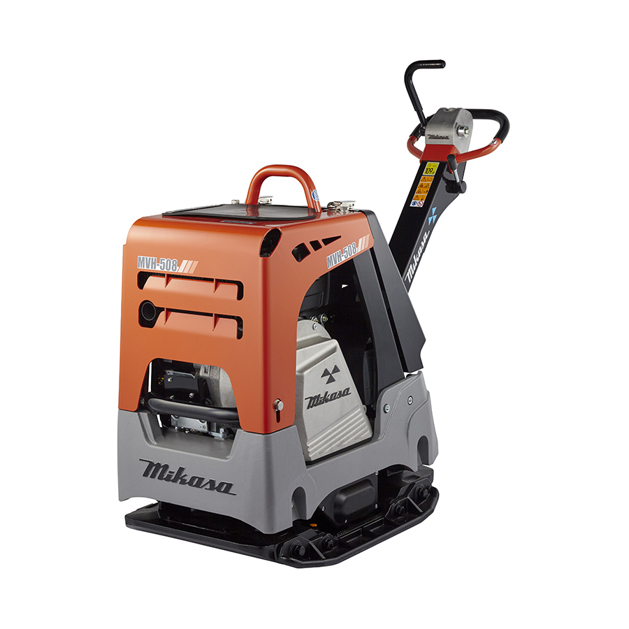
- Page 1 REVERSIBLE COMPACTOR MVH-308 MVH-408 MVH-508 SERIES SERVICE MANUAL...
-
Page 2: Table Of Contents
TABLE OF CONTENTS 1. INTRODUCTION 2. WARNING SIGNS 3. CAUTIONS FOR MAINTENANCE TO SECURE SAFETY Work Site ....................Clothes And Protective ................Cautions During Refuelinglothes And Protective ........Prevention Of Burn And The Accident Of Getting Caught ......Tools And Equipment ................ -
Page 3: Introduction
To improve the performance and quality of this machine, the change might be made in this machine without notice. If you have any questions, please contact with our distributor. For parts list, Mikasa WEB parts list is available at our homepage (http://www.mikasas.com/). -
Page 4: Clothes And Protective
3.2 Clothes And Protective CAUTION To work safely, wear work clothes of appropriate size, and use suitable protective gear such as helmet and safety shoes. The work clothes that do not fit the body size might result in unpredicted injury because the clothes easily get caught by rotating part of the machine. -
Page 5: Use Of Genuine Parts And Appropriate Oil And V-Belt
3.7 Use Of Genuine Parts And Appropriate Oil And V-belt CAUTION Always use genuine parts. If inappropriate parts are used, not only it will shorten the machine life, but it might lead to unpredicted accident. 3.8 Tightening Torque Of Bolts And Nuts WARNING Tighten bolts and nuts with the tightening torque specified in this maintenance manual. -
Page 6: Tools
4 TOOLS 1. Wrench 10mm 12mm 13mm 14mm 17mm 19mm 22mm 24mm 27mm Offset wrench/Socket wrench/Adjustable wrench 2. Hexagonal wrench 3/16inch 5mm 8mm 10mm 14mm 3. Plier 4. External snap ring plier/Internal snap ring plier(bent type can be also used) 5. -
Page 7: Inspection Procedure
5.INSPECTION PROCEDURE 5.1 Appearance Check Assembly condition of each component (bolt loosening, defective parts, etc.) Damage on machine body Oil check (oil level, dirtiness) Engine oil (when shipped, SAE10W30) (For oil level, please see the table below.) Vibrator oil Hydraulic oil (forward/backward travel) V-belt check (tension, scratch, crack, deterioration, etc.) Anti-vibration rubber check (scratch, crack, setting, deterioration, etc.) 5.2 Operation Check... -
Page 8: Specification
6 SPECIFICATION Main Dimensions Overall Length 1540 1540 1570 Overall Height (Handle) 1030 1030 1030 Overall Width 445(595,745) 445(595,745) 500(650,800) Compacting Board 445(595,745) Width 445(595,745) 500(650,800) Length Weight Operating Weight 345(360,375) 341(356,371) 408(423,438) Engine Manufacturer/Type HATZ,1B30 YANMAR,L70N6 HATZ,1B50 Air-cooled 4-cycle Air-cooled 4-cycle Air-cooled 4-cycle Type Of Engine... - Page 9 Main Dimensions Overall Length 1540 1540 1570 1030 1030 1030 Overall Height (Handle) 445(595,745) 445(595,745) 500(650,800) Overall Width Compacting Board 445(595,745) 445(595,745) 500(650,800) Width Length Weight 310(325,340) 307(322,337) 364(379,394) Operating Weight Engine Manufacturer/Type HONDA,GX270 ROBIN,EX27 HONDA,GX390 Air-cooled 4-cycle Air-cooled 4-cycle Air-cooled 4-cycle Type Of Engine petrol engine...
-
Page 10: Cautions Before Maintenance Work
7 CAUTIONS BEFORE MAINTENANCE WORK Disassembly and assembly of this machine, with inspection and change of vibrator oil included, should be done on a horizontal surface area. Before disassembly and assembly, understand well the normal assembly condition so that you will not make assembly error. -
Page 11: Disassembly And Assembly
8 DISASSEMBLY AND ASSEMBLY 8.1 How To Remove The Battery CAUTION Remove the stopper at the two locations Pay sufficient attention so that the battery ter- on the top portion of the rear cover to minal will not touch the frame. open the rear cover.(Fig.1) 8.2 Control Part MVH-308... - Page 12 Remove the wire terminal on engine side. Assembly Assemble with the reversed procedure CAUTION of disassembly, but be careful about the following points. Be very careful not to have your fingers Fix the wire (coupler) inside rear cover get caught by the hand pump spring. (18) with cable tie certainly.
-
Page 13: Vibrator Partontrol
Apply Loctite #243 to the all bolts for as- sembling the BASE AND ENGINE. When installing the clutch, put the shoe side of it to engine side. Use HDPF type V-belt for Mikasa genuine parts. 8.4 Vibrator Partontrol During disassembly and assembly, be Fig.8... - Page 14 Remove the bearing outer for seal cap Remove each 2 bolts (7 & 12), then side with the bearing remover, then remove 4 eccentric rotator (6). (Fig.11) remove the driven shaft (11) AY from the Bolt for drive shaft side Eccentric rotator(6) inside of vibrator case.
- Page 15 Apply the grease to the drive gear (4) Disassembly of drive shaft (2) AY before press fitting. Remove 4 bolts (34), then remove bearing The punch mark of drive gear (4) cover (27). should put the pulley side. (Fig.19) When removing the bearing cover, use Be careful about the direction of the screw hole for bearing cover removal.
- Page 16 Press fit the bearing outer of pulley side by Assemble the O-ring (30) to the bearing tightening the center bolt of bearing inser- cover (27), then assemble it to the vibrator tion puller. (Fig. 22) case for the bearing cover side. After as- sembled the bearing cover, check the PULLER SIDE thrust gap of drive shaft.
- Page 17 In case of the driven gear is assembled PULLEY SIDE (INSIDE:STRAIGHT) correctly, when pulling out the piston Bolt 16 30(P1.5)(12) rod, the punch mark of driven gear and Eccentric rotator (6) the threaded holes for eccentric rotator of driven shaft should be set in the same straight line.
- Page 18 Insert from the piston side of driven shaft CAUTION (11) AY into the vibrator case, then align Check the bolts size. the punch mark between the drive gear Apply Loctite #263 to the each bolts (7 & and driven gear. (Fig. 33) 12).
- Page 19 By the above steps, the assembly of the vibrator is completed. As a final step, turn the drive shaft with your hand to make sure that it rotates smoothly. If it does not rotate smoothly, adjust it by hitting the side of gear with a plastic hammer lightly.
-
Page 20: Hand Pump & Accumulator Cp
Fix the pump head with the vise. 8.5 Hand pump & Accumulator CP (Fig. 40) CAUTION Fix the handle insertion part of the pump head. During disassembly and assembly, be careful not to damage each part. Replace the O-ring, oil seal, and packing with a new one. - Page 21 Assembly Assemble with the reversed procedure of disassembly, but be careful about the following points. Degrease and clean the each parts. Be careful not to damage each parts, during assembly. Replace the O-ring and dust seal with a new one. Apply the molybdenum grease to the O-ring, dust seal and sliding area.
- Page 22 d. Assemble the springs to the accumula- By the above steps, the assembly tor. Then, compress the springs with the of hand pump and accumulator is spring compression tool until the thread on completed. the end of accumulator shaft is out com- pletely.
-
Page 23: Regular Check And Adjustment
9 REGULAR CHECK AND ADJUSTMENT Do inspection and maintenance work in a place with a flat and hard surface to CAUTION keep the machine stable, after stopped the engine certainly. 9.1 Inspection and Maintenance Chart To use the machine in good condition all the time, always do the inspection and maintenance according to the following inspection sheet. -
Page 24: Opening The
Diesel Engine 9.3 Opening The Front Cover CAUTION Hold the hook and the front side of front cover, and pull up to open position. During disassembly a maintenance work (Fig.54) in a place with a flat and hard surface to keep the machine stable. -
Page 25: Cleaning The Air Cleaner
Clean Dust Pot inside with water and neu- tral detergent. CAUTION Do not use organic solvent like paint thinner, which may cause damage or deformation of Engine oil drain Dust Pot. (Drain bolt) Latch up securely to return Dust Pot to Air Cleaner.(Fig. -
Page 26: Checking/Changing The Vibrator Oil
CAUTION ! Oil gauge (19mm wrench) Stop the engine when inspecting or ● Effective changing the V belt. Be careful not to have your hand or ● clothes get caught between the V belt and the clutch. Always wear work gloves. Drain plug Inspection of clutch ●... -
Page 27: Battery
Changing the hydraulic oil ● Remove the plug cap of the hand pump. Then remove the breather plug (with 24mm wrench) before removing the hy- draulic hose connected to the cylinder on the vibrator side. Set the run lever to reverse, then drain the hydraulic oil from the pump.(Fig.62, 63) Handle cover... - Page 28 HOUR TACHOMETER Battery checker DIESEL ENGINE TACH &HOUR METER Battery of main Engine crank case Fig.66 machine side CAUTION If an old battery is used, even when the bat- tery checker is not lighted (indicating charg- ing level low), the cell starter might not oper- ate because of low charging level.
- Page 29 Mountable battery size table SIZE 55B24L(JIS) No.51R(BCI) DIN 55Ah or equivalent Replacement MVH-308 JIS/BCI TYPE Maximum capacity DIN TYPE Maximum capacity 55B24L (JIS) No.51R(BCI) 75D23L(JIS) No.35(BCI) Replacement MVH-408 DIN 55Ah or equivalent Maximum capacity 75D23L(JIS) No.35(BCI) DIN 75Ah or equivalent Replacement MVH-508 Maximum capacity...
-
Page 30: Troubleshooting
10 TROUBLESHOOTING 10.1 Gasoline Engine (1) Starting problems Bridging the igniter plug. Carbon accumulated on the igniter plug. Short circuit due to insulation problems of Electricity reaches the igniter plug. the high voltage cable. Inappropriate spark gap Fuel is supplied, but the igniter plug does Short circuit of the ON-OFF switch not ignite. -
Page 31: Diesel Engine
10.2 Diesel Engine (1) Starting problems (A) In case of compression problems Intake/exhaust valve upthrust No compression at all Decompressor adjustment problems Contact with seat not close enough. Piston ring wear Almost no compression Cylinder wear Cylinder, cylinder head mating surface problems Nozzle seat looseness (B) In case of inappropriate fuel injection inside the combustion chamber Clogging of the tank cap air hole. -
Page 32: Main Body
Valve open/close timing inappropriate Engine revolution Clogged exhaust hole, muffler does not increase. Overload Piston, cylinder ring wear Nozzle hole clogging Piston ring stuck Wrong assembly (upside down) of piston ring Inappropriate injection timing Inappropriate valve open/close timing Looseness of injection pump joint Leakage from fuel passage Fuel consumption too Clogging of the air cleaner element... -
Page 33: Wiring Diagram
11 WIRING DIAGRAM MVH-308DSY MVH-408DSY SUMITOMO Sky-blue Oil pressure switch Orange SUMITOMO (White) Dynamo 114399-78260 Starter (Green/ (Green/ White) White) BOLT (Green/ (Green/ White) White) White YAZAKI Regulator White Black BODY EARTH White Green YAZAKI MVH-308DSY-PAS MVH-408DSY-PAS SUMITOMO Compaction ISO 8820-3 sensor panel Sky-blue Oil pressure... - Page 34 MVH-308DSZ MVH-408DSZ Starter Dynamo Battery No.3: Relay drive BOLT Regulator Oil pressure CB104 switch CA104 Buzzer CB104 CA104 Green Black MVH-308DSZ-PAS MVH-408DSZ-PAS Starter Dynamo Battery No.3: Relay drive BOLT Regulator Oil pressure CB104 CA104 switch Buzzer CA104 CA104 CA104 CB104 Green CB104 Black...
- Page 35 MVH-508DSZ Starter Dynamo Battery No.3: Relay drive BOLT Regulator Oil pressure CB104 switch CA104 Buzzer CA104 CB104 Green Black MVH-508DSZ-PAS Starter Dynamo Battery No.3: Relay drive BOLT Regulator Oil pressure CB104 switch CA104 Buzzer CA104 CA104 CA104 CB104 CB104 CB104 ISO 8820-3 TYPE,F CA104...
- Page 36 HEAD OFFICE No.4-3, Sarugakucho 1-chome, Chiyoda-ku, Tokyo, 101-0064, Japan...
Need help?
Do you have a question about the MVH-308 Series and is the answer not in the manual?
Questions and answers