
Subscribe to Our Youtube Channel
Related Manuals for Mikasa MVH-408DSZ


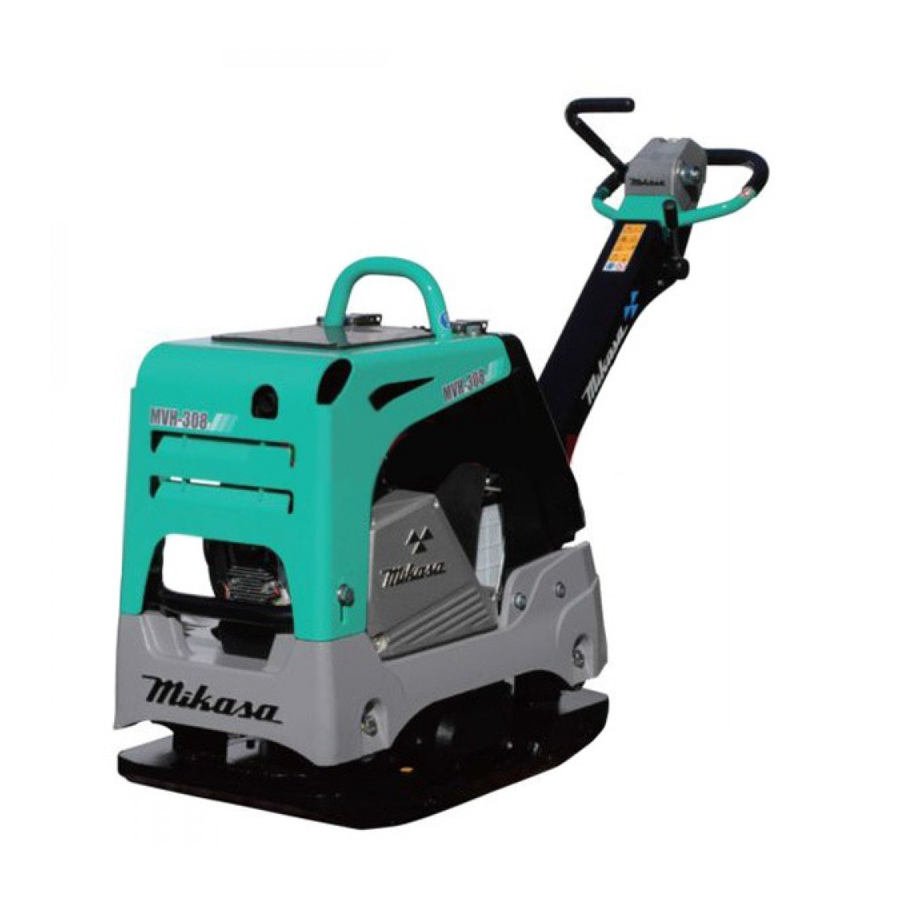
Summary of Contents for Mikasa MVH-408DSZ
- Page 1 REVERSIBLE COMPACTOR MVH-308 MVH-408 MVH-508 INSTRUCTION MANUAL Contents of Declaration of Conformity Please refer the EC DECLARATION OF CONFORMITY in this manual as well. 402-07403...
- Page 2 2) Manufacturer’s name and address. 4-3, Sarugaku-cho 1 chome, Chiyoda-ku, Tokyo101-0064, Japan Yoshiharu Nishimaki, engineer 3) Name and address of the person who keeps the R. & D. Division, Mikasa Sangyo Co., Ltd. technical documentation. Shiraoka-city, Saitama, Japan 4) Type: Vibratory Plates...
- Page 3 2) Manufacturer’s name and address. 4-3, Sarugaku-cho 1 chome, Chiyoda-ku, Tokyo101-0064, Japan Yoshiharu Nishimaki, engineer 3) Name and address of the person who keeps the R. & D. Division, Mikasa Sangyo Co., Ltd. technical documentation. Shiraoka-city, Saitama, Japan 4) Type: Vibratory Plates...
- Page 4 Italian Garanzia di Qualità totale ) DICHIARAZIONE “CE” DI CONFORMITÁ 13. Nom et adresse de l'organisme notifié Nome e indirizzo Fabbricante 14. Mandataire dans la Communaute Europeenne Nome e indirizzo della persona che conserva la 15. Directive concernee documentazione tecnica Est egalement conforme aux dispositions de la directive <<emission sonores des equipements utilises a l'exterieur Tipo: Piastre vibranti...
-
Page 5: Table Of Contents
Table of contents INTRODUCTION ..................APPLICATION, STRUCTURE AND POWER TRANSMISSION ....WARNING SIGNS ..................CAUTIONS FOR SAFETY................ General Cautions Refueling Precautions Location And Ventilation Precautions Precautions Before Starting Precautions During Work Lifting Precautions Transportation And Storage Precautions Maintenance Precautions Label Position Descriptions Of Symbols Used On Warning Labels 4.10 Control Unit Positions And Names... -
Page 6: Introduction
For inquiries about repair parts, parts lists, service manuals, and repairs, please contact the store where you purchased ● the product, our sales office, or the Mikasa Parts Service Center. For parts lists, please visit our homepage at: http://www.mikasas.com/ where you can access Mikasa WEB parts lists. -
Page 7: Warning Signs
3.WARNING SIGNS The triangle shaped marks used in this manual and on the decals stuck on the main body indicate common hazards. Be sure to read and observe the cautions described. Warning labels indicating hazards to humans and to equipment. !... -
Page 8: Refueling Precautions
4.2 Refueling Precautions DANGER ! Always refuel in a well ventilated area. ● Make sure to stop the engine and wait until the engine cools down when refueling. ● Select a flat surface area with no flammable material around for refueling. Be careful ●... -
Page 9: Maintenance Precautions
4.8 Maintenance Precautions WARNING ! Appropriate maintenance is required to ensure safe and efficient operation of the ● machine. Always pay attention to the machine’s condition and keep it in good condition. Pay special attention to the parts used for lifting, if they are not maintained properly, it might result in a serious accident. -
Page 10: Label Position
※ The illustration is shown for model, "MVH-308"... - Page 11 DECAL COMPASS MARK 94MM Diesel Only 9202-17650 DECAL COMPASS MARK 110MM Diesel Only 9202-14750 DEAL,CAUTION ICONS/V-TYPE 9202-17130 DECAL,MIKASA MARK(W)200L 9202-17110 DECAL, MIKASA MARK 35X70 9202-18140 DECAL, E/G RPM 3400 308D 9202-18130 DECAL, E/G RPM 3600 308G 9202-18150 DECAL, E/G RPM 2400 408D,508D...
-
Page 12: Descriptions Of Symbols Used On Warning Labels
4.10 Descriptions Of Symbols Used On Warning Labels ① Do not use. (For rollers) ② ③ ⑤ ④ ⑨ NPA-1476 MVH-308GH NPA-1473 MVH-408GH ⑥ ⑩ Do not use. ⑧ (For rollers) ⑦ NPA-1475 NPA-1474 Refueling Hazard. Read the manual carefully. ⑥... -
Page 13: Control Unit Positions And Names
4.11 Control Unit Positions And Names Fuel tank cap Hour / tacho meter Breather plug (Fuel inlet) Handle lock Rubber cover (with plug cap) (Stored position) Key switch Oil filler for engine (without oil gauge) Hand pump Hook Compaction sensor Grip (COMPASS) Cyclone cleaner... -
Page 14: Specification
5.SPECIFICATION MVH-308DSZ MVH-308DSY MVH-408DSZ MODEL MVH-308DSZ-PAS MVH-308DSY-PAS MVH-408DSZ-PAS Main Dimensions Overall Length 1540 1540 1570 Overall Height (Handle) 1030 1030 1030 Overall Width 445(595,745) 445(595,745) 500(650,800) Compacting Board Width 445(595,745) 445(595,745) 500(650,800) Length Weight Operating Weight 345(360,375) 341(356,371) 408(423,438) Engine... - Page 15 MODEL MVH-308GH MVH-308GE MVH-408GH Main Dimensions Overall Length 1540 1540 1570 1030 1030 1030 Overall Height (Handle) Overall Width 445(595,745) 445(595,745) 500(650,800) Compacting Board Width 445(595,745) 445(595,745) 500(650,800) Length Weight 310(325,340) 307(322,337) 364(379,394) Operating Weight Engine HONDA,GX270 ROBIN,EX27 HONDA,GX390 Manufacturer/Type Air-cooled 4-cycle Air-cooled 4-cycle Air-cooled 4-cycle...
-
Page 16: Appearance
6.APPEARANCE MVH-308 MVH-408 ※ The illustration is shown for model, "MVH-308" Stored position NPA−1764 A Working position MVH-308: 860mm MVH-408: 900mm MVH-308: 445mm MVH-408: 500mm MVH-308: 1540mm MVH-408: 1575mm Extension plate (option) MVH-308 (Standard:595mm, Wide:745mm) MVH-408 (Standard:650mm, Wide:800mm) MVH-508 Stored position NPA−1765... -
Page 17: Inspection Before Operation
7.INSPECTION BEFORE OPERATION Part inspection sheet before work start Check point Check item Visual inspection Crack、Skewness Front cover & center cover Falling off、Breakage、Crack、Looseness and falling off of bolt & nuts Fuel tank Leak、Quantity of oil、 Dirt Fuel system Leak Fuel filter Dirt Engine oil Leak、Quantity of oil、 Dirt... -
Page 18: Handle
7.4 Handle Lock lever Fuel tank cap The height of the handle is adjustable for your comfort.(Fig.5) Adjusting Handle height ※ Only for HATZ engine ① Loosen the wing nut.Turn the grip clockwise to raise the handle or counter clockwise to lower the handle.When the handle is raised to the desired height, tighten the wing nut. - Page 19 Move the throttle lever to the idle position. After the engine has started, while you hear (Fig. 8) some explosion loud noise, gradually move back the choke lever until it is wide open. (Fig.12) When the choke lever is set to “Start”, gradually move it back toward the “Op- Throttle lever eration”...
- Page 20 Turn the key further to the “START” position Diesel Engine to start the engine. After the engine is Set the fuel cock lever to the “ON” position started, take your hand off the key.(Fig.16) to let the fuel flow.(Fig. 14) After the engine revolution rises, the buzzer (Only for YANMAR engine) stops.
-
Page 21: Operation
After the engine has started, warm up the When this machine is used on ground that con- engine at low speed for 2 to 3 minutes. This tains clay, the ground surface tends to stick to is especially important in cold weather. the vibrating board, and the machine travel speed becomes slower. - Page 22 If that happens, because you cannot expect Normal operation (Green: Lighted) sufficient compaction, do ground improve- Vibration abnormality (Green: Flashing) ment work before proceeding with the com- Compaction limit (Yellow + Red: Lighted) paction process. (Fig. 26) Soil problem (Only red: Lighted) Ground trouble or soft ground CM- 0 1 (Red only: Lighted)
-
Page 23: Stopping The Machine
9.STOPPING THE MACHINE Gasoline Engine Move the throttle lever to idle position. Throttle lever Run the engine for 3 to 5 minutes at low speeds to cool it down before stopping. Turn the engine switch to the OFF position, Handle Idle position then the engine stops. -
Page 24: Transportaion And Storage
10.TRANSPORTAION AND STORAGE ● Store in a dry area away from direct sunlight 10.1 Loading And Unloading after putting the cover over the machine to prevent dust and dirt buildup. WARNING ! ● Do not leave the machine outdoors. Keep it ●... -
Page 25: Regular Check And Adjustment
11.REGULAR CHECK AND ADJUSTMENT 11.1 Inspection And Maintenance Schedule Table Check items Oils Check frequency Check parts Daily Appearance Flaw, deformation (before starting) Fuel tank Leakage, oil level, dirt Light oil, gasoline Fuel system Leakage, oil level, dirt Engine oil Leakage, oil level, dirt Engine oil Shock absorber... -
Page 26: Open The
11.2 Opening The Front Cover Diesel Engine For a comfortable maintenance work. Hold the hook and the front side of front cover, and pull up to open position.(Fig.38) CAUTION ! ● Do maintenance work in a place with a flat and hard surface to keep the machine Open position stable. -
Page 27: Changing The Engine Oil
11.3 Changing The Engine Oil CAUTION ! Be careful to avoid pinched fingers. ● Perform the first engine oil change after 20 hours of operation, then change at every Clean Dust Pot inside with water and neu- 100 hours.(Fig.41) tral detergent. CAUTION !... -
Page 28: Checking/Changing The Vibrator Oil
Installing the V-belt ● 11.7 Checking/Changing The Hydraulic Oil Set the V-belt on the lower side of the vibra- ● Check the hydraulic oil tor pulley. Push the V-belt to the left side of Check the hydraulic oil at every 100 hours’ the upper clutch. -
Page 29: Battery
Pour hydraulic oil(550cc) from the hand CAUTION ! pump breather plug attachment hole. (Fig.47) If an old battery is used, even when the bat- tery checker is not lighted (indicating charging Remove the air releasing plug of vibrator level low), the cell starter might not operate cylinder. - Page 30 For assembly, take the reverse steps de- Battery holder scribed above, but when attaching the bat- tery terminal, start with the red terminal of the plus side. Also, attach securely so that it will not get loosened by vibration. CAUTION !...
-
Page 31: Troubleshooting
12.TROUBLESHOOTING 12.1 Gasoline Engine (1) Starting problems Bridging the igniter plug. Carbon accumulated on the igniter plug. Short circuit due to insulation problems of Electricity reaches the igniter plug. the high voltage cable. Inappropriate spark gap Fuel is supplied, but the igniter plug does Short circuit of the ON-OFF switch not ignite. - Page 32 12.2 Diesel Engine (1) Starting problems (A) In case of compression problems Intake/exhaust valve upthrust No compression at all Decompressor adjustment problems Contact with seat not close enough. Piston ring wear Almost no compression Cylinder wear Cylinder, cylinder head mating surface problems Nozzle seat looseness (B) In case of inappropriate fuel injection inside the combustion chamber Clogging of the tank cap air hole.
- Page 33 Valve open/close timing inappropriate Engine revolution Clogged exhaust hole, muffler does not increase. Overload Piston, cylinder ring wear Nozzle hole clogging Piston ring stuck Firing problem with Wrong assembly (upside down) of piston ring white smoke Inappropriate injection timing (when unloaded) Inappropriate valve open/close timing Looseness of injection pump joint Leakage from fuel passage...
-
Page 34: Wiring Diagram
13.WIRING DIAGRAM MVH-308DSY MVH-408DSY SUMITOMO 6040-2111 AV0.5(Sky-blue) Oil pressure switch DC12V AV0.5(Orange) SUMITOMO 121252-39450 6030-2981 (White) Dynamo (Black/ Green) 114399-78260 CA104 Starter DC12V 0.8kW CB104 (Green/ (Green/ White) White) BOLT CA104 AV20 + CB104 CB104 CB104 Starter switch CA104 CA104 (Green/ (Green/ -... - Page 35 MVH-308DSZ MVH-408DSZ Starter Dynamo DC12V 1.0kW Battery Starter switch No.3: Relay drive 55B24L BOLT AV20 + AV20 - Regulator Oil pressure switch CB104 (White) Pulse CA104 Buzzer CB104 CA104 Green Black MVH-308DSZ-PAS MVH-408DSZ-PAS Starter DC12V 1.0kW Dynamo Battery Starter switch No.3: Relay drive...
- Page 36 MVH-508DSZ Starter Dynamo DC12V 1.0kW Battery Starter switch No.3: Relay drive 75D23L BOLT AV20 + AV20 - Regulator Oil pressure switch CB104 (White) Pulse CA104 Buzzer CA104 CB104 Green Black MVH-508DSZ-PAS Starter DC12V 1.0kW Dynamo Battery Starter switch No.3: Relay drive 75D23L BOLT AV20...
- Page 37 memo - - - - - - - - - - - - - - - - - - - - - - - - - - - - - - - - - - - - - - - - - - - - - - - - - - - - - - - - - - - - - - - - - - - - - - - - - - - - - - - - - - - - - - - - - - - - - - - - - - - - - - - - - - - - - - - - - - - - - - - - - - - - - - - - - - - - - - - - - - - - - - - - - - - - - - - - - - - - - - - - - - - - - - - - - - - - - - -...
- Page 40 HEAD OFFICE No.4-3, Sarugakucho 1-chome, Chiyoda-ku, Tokyo, 101-0064, Japan...
Need help?
Do you have a question about the MVH-408DSZ and is the answer not in the manual?
Questions and answers