Table of Contents
Advertisement
Quick Links
USER GUIDE TB-9021
711 Charge Analyzer
Operation and Maintenance
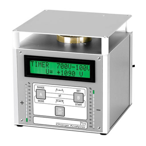
Figure 1. SCS
711
Charge Analyzer.
Description
The SCS 711 Charge Analyzer is an electronic test
instrument designed for ease of use. The lightweight
and compact construction offers great versatility in the
workplace. It can be used as a laboratory analytical
tool, evaluating the performance of ionizing equipment,
static-protective packaging, work surfaces and personnel
grounding systems. It is also very effective for use as a
demonstration tool in employee static awareness training
programs.
All parameter settings are controlled via a built-in
EEPROM. These parameters are defaulted to when
the 711 Charge Analyzer is switched on again. In case
of a malfunction, the unit will display a corresponding
message and then automatically switch off.
The 711 Charge Analyzer operation works according to
the field mill-principle. The field meter is a parametric
amplifier. An electrostatic field induces a charge
on the sensor electrode, generating an AC current
that is proportional to the field strength. An amplifier
measures this current without reducing the energy of the
electrostatic field in average time.
Important Notice: Avoid extreme discharge of the
rechargeable batteries. If the batteries require charging,
do not allow the unit to sit idle for a period of time without
first fully charging the batteries.
The 711 Charge Analyzer is powered by built-in
rechargeable NiMH-batteries or an AC wall plug-in
adaptor. When the unit is powered from the rechargeable
batteries, the LCD-display will not be back illuminated
to extend battery life. This power saving feature will
initiate within 60 seconds after the last measurement
or button depression. Also during battery operation,
the continuous LED-bar indication changes to a single
(momentary) action.
TB-9021 Page 1 of 12
April 2017
Test Equipment Depot - 800.517.8431 - 99 Washington Street Melrose, MA 02176
In case of a low battery power condition, the 711 Charge
Analyzer automatically switches off, first displaying LOW
BATTERY then SWITCHING OFF UNIT. If this occurs,
continued operation of the 711 Charge Analyzer can be
maintained through the AC adaptor. Recharge time is
approximately 14 hours with unit off, when batteries are
fully discharged.
Two vertical LED bars indicating 0 - 100% charge level
and polarity are located on the left and right sides
of the front panel. The alphanumeric LCD-display is
the information center of the 711 Charge Analyzer
and allows the user to observe the principles of static
protection. The unit's high accuracy makes it well suited
for product performance analysis.
All interfacing connections are made at the rear of the
unit. The SCS 711 Charge Analyzer can be connected
to a y (t)-recorder via the ± 2 volts analog output.
A Remote Field Sensor Probe is connected through a
4-Pin circular socket located on the rear of the unit. The
sensor operates on the same measurement principle as
described above. This feature allows to the user to make
measurements by means of a hand-held or fixed position
probe in remote locations, where it may be impossible
to position the 711 Charge Analyzer. Measurement
distances with the probe are 1, 2, 5, 10 and 20
centimeters. The built-in microprocessor automatically
converts the measured field strength via the chosen
distance into a charge of an equivalent potential in volts.
The display automatically switches from volts to kilovolts.
The following operating functions will be automatically
activated, when the appropriate electrode or sensor is
connected to the base unit.
The 711 Charge Analyzer comprises of four types of
independent operating functions:
• Static field meter sensor – Measuring electrostatic
fields
• Voltmeter - Measuring the potential on charged objects
• Static decay time – Measuring charge-decay and
balance of ionizing equipment by charge plate monitor
(CPM) method
• Remote Field Sensor Probe – Measuring the
potential on charged objects in confined areas.
Change between these operating functions will
be verified on the display as CHANGE MODE OF
OPERATION.
TestEquipmentDepot.com
© 2017 DESCO NDUSTRIES, NC.
Employee Owned
Advertisement
Table of Contents

Subscribe to Our Youtube Channel
Related Manuals for SCS 711


Summary of Contents for SCS 711
- Page 1 USER GUIDE TB-9021 711 Charge Analyzer Operation and Maintenance In case of a low battery power condition, the 711 Charge Analyzer automatically switches off, first displaying LOW BATTERY then SWITCHING OFF UNIT. If this occurs, continued operation of the 711 Charge Analyzer can be maintained through the AC adaptor.
-
Page 2: Specifications
Packaging Static Decay Time 0.1 seconds - 99.9 seconds 1 Charge Analyzer Offset-voltage Time 0 seconds (Indefinite time, 1 Plate Electrode CPM in floating mode) 1 Cup Electrode 1 - 10 seconds (1 second 1 Cylinder Electrode steps) 1 Sensor Red Cover 10 - 60 seconds (10 second 1 Measuring Lead, 1m steps) - Page 3 • Connect the attached ground wire on rear panel to an electrical ground before operating the 711 Charge Analyzer • Do not use if the 711 Charge Analyzer housing or power supply are damaged; • Do not attempt to modify or repair – no user serviceable parts inside –...
-
Page 4: Voltmeter Operation
1. Remove the plate electrode and red sensor cover from the 711 Charge Analyzer, if attached. Voltage Measurement Ranges: 2. Mount the gold cup electrode (a) to the top of the 711 Manual/Auto; 25V, 100V, 500V, 1000V, & 5000V Charge Analyzer and secure with the attached long- Meter display symbols in Voltmeter mode knurled screws. - Page 5 Note: If you should press the “B” button (SETUP), you recommended by the manufacturer. Perform the same will have to switch off the Charge Analyzer 711 to get body movements and observe the reduced or back into the Voltmeter mode.
- Page 6 Note: The Start voltage can only be adjusted from 600 to 1100 volts. The Stop voltage can only be adjusted from 1 to 500 volts. The maximum period of time that the 711 Figure 8. SCS Charge Analyzer Static Decay Time allows for the measurement of the start to stop voltage is and Balance Operation.
- Page 7 “B” button until the display reads A<YES electrode. & NO>B. 2. Mount the plate electrode (b) to the 711 Charge 7. Press the “A” YES button to verify and store the start Analyzer. Be sure that the red sensor cover (e) is voltage value.
- Page 8 (ionizer balance) mode. The display will 1. Attach the three metal-spacers (j) by screwing into indicate OFFS-TIME (starting timer at set time) and U the three locations at the rear of the SCS 711 Charge (current charge plate voltage). Analyzer.
- Page 9 Remote Field Sensor Probe Setup 2. Position the 711 Charge Analyzer in front of the ionizer blower with the display facing upward. The following procedure activates the SCS 711 Charge 3. Measure the static decay rate and offset balance by Analyzer for use with the Remote Field Sensor Probe.
-
Page 10: Analog Output
711 Charge Analyzer Internal Sensor: sensor equals 10 cm and the “U” value indicates 500 1. Mount the cup electrode (a) to the top of the 711 volts, using chart below, then the V/m is in this case Charge Analyzer and perform the zeroing function 5,000 volts. -
Page 11: Maintenance
• The 711 Charge Analyzer contains a NiMH battery pack Safety Information and circuitry that contains lead in the solder. At the end of service life, dispose of the 711 Charge Read, understand, and follow all safety information Analyzer in accordance with federal, state and contained in this User’s Guide prior to use of the SCS... -
Page 12: Regulatory Information
The following information is only for EU-members States: Analyzer; The mark shown to the right is in compliance with Waste • Do not use if the SCS 711 Charge Analyzer housing or Electrical and Electronic Equipment Directive 2002/96/ power supply are damaged;...
Need help?
Do you have a question about the 711 and is the answer not in the manual?
Questions and answers