Table of Contents
Advertisement
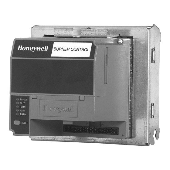
R7140G,L,M
Burner Control Modules
APPLICATION
The Honeywell R7140G,L,M Burner Control Modules are
microprocessor-based integrated burner controls for
automatically fired gas, oil or combination fuel single burner
applications. The Burner Control Module system consists of a
Relay Module, Q520A Subbase, Amplifier and Purge Card.
Options include S7800 Keyboard Display Modules (KDM).
The R7140 Burner Control Modules directly replace many
BC7000 PM720G,L,M, and many R4150G,L,M and
R4140G,L,M units using the existing Q520A 20-terminal
Wiring Subbase.
The R7140 can be demonstrated or tested on the FSP5004
tester. Note that the R7849 UV Amplifier or the R7851 Optical
Flame Amplifier cannot be tested.
The R7140G,L,M is programmed to provide a level of safety,
functional capability and features beyond the capacity of
conventional controls.
Functions provided by the R7140G,L,M include automatic
burner sequencing, flame supervision, system status
indication, system or self-diagnostics and troubleshooting.
INSTALLATION INSTRUCTIONS
FEATURES
• Device status available to ModBus™ through S7810M
card or S7800A1001 Series 5 Keyboard Display.
• Safety features:
— Interlock check.
— Closed loop logic test.
— Dynamic AMPLI-CHECK™.
— Dynamic input check.
— Dynamic safety relay test.
— Dynamic self-check logic.
— Expanded safe-start check.
— High Fire Purge Switch test (R7140L only).
— Internal hardware status monitoring.
— Low Fire Start Switch test.
— Tamper resistant timing and logic.
• Access for external electrical voltage checks.
• Application flexibility.
• 0.8 or 3.0 second Flame Failure Response Time
(FFRT), depending on amplifier selected.
• Dependable, long-term operation provided by
microcomputer technology.
• Five LEDs for sequence information. See Fig. 1.
• Five function Run/Test Switch.
• Interchangeable plug-in flame amplifiers.
• Nonvolatile memory; R7140 retains history files and
sequencing status after loss of power and can be
viewed using the Keyboard Display Module
S7800A1001 (sold separately).
• Report generation (optional).
NOTE: Check Service Notes on page 7 and Static Checkout
on page 25 prior to installation of R7140.
• Burner controller data (optional):
— Lockout/alarm status.
— Total cycles of operation.
— Total hours of operation.
• Status of configuration jumpers.
• Status of Run/Test Switch.
66-1153-2
Advertisement
Table of Contents


Need help?
Do you have a question about the R7140G and is the answer not in the manual?
Questions and answers