Advertisement
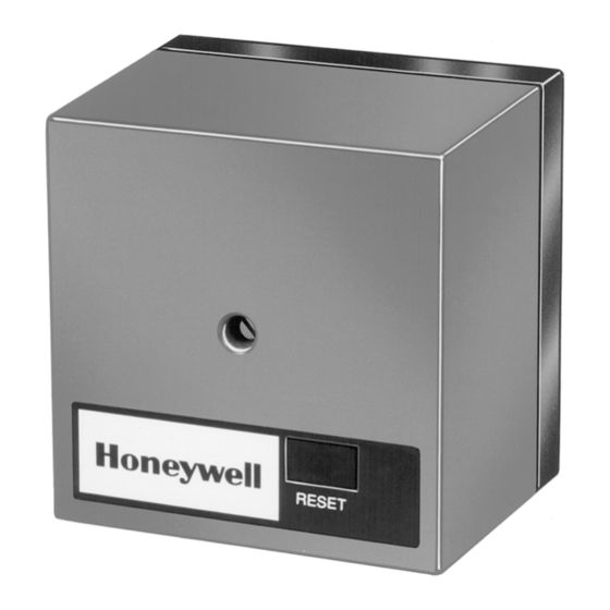
The R7795 Flame Safeguard Primary Control
provides flameout protection plus automatic
control of commercial and industrial gas and
oil burners. Models provide intermittent pilot
or interrupted pilot with delayed main valve.
Integral solid state color-coded flame amplifiers:
R7795A,C for ultraviolet detection systems (purple).
R795B,D for rectification detection systems (green).
See Table 1.
Solid state plug-in ST95A Purge Timers provide
prepurge timings of 1.5, 7, 10, 30, 60, or 90 seconds.
Includes terminals for connection of a line voltage
airflow switch to prove airflow from the start of
prepurge through the run period.
Mounts on a Q795A Subbase with two captive
screws. All electrical connections are automatically
provided between the device and subbase. Wiring
terminals are accessible for testing.
Meter jack on amplifier board for measuring flame
signal with system in operation.
Internal light-emitting diode (LED) indicates pres-
ence of flame signal.
R7795A,B,C,D
Flame Safeguard
Primary Controls
Field selectable ten or four second trial for pilot
flame ignition.
Powered alarm terminal to operate an external line
voltage alarm on safety lockout.
R7795 models are available with either intermittent
pilot (interrupted ignition) or interrupted pilot and
delayed main valve. See Table 2.
Run-Test switch on interrupted pilot/delayed main
valve models.
Safe-start feature prevents start-up with lockout if
flame or a flame simulating failure exists.
Recycle or lockout on flame failure is field selectable.
Safety switch must be manually reset after lockout.
Meets Underwriters Laboratories, Canadian Stan-
dards Association, and Factory Mutual Approved
standards.
CONTENTS
Specifications ................................................. 2
Ordering Information ..................................... 2
Detailed Operating Sequence ........................ 4
Installation ..................................................... 8
Checkout ....................................................... 11
Troubleshooting ........................................... 17
Service .......................................................... 19
B. M. • Rev. 9-93 • ©Honeywell Inc. 1993 • Form Number 66-2001-2
1
66-2001-2
Advertisement

Related Manuals for Honeywell R7795B


Summarization of Contents
Specifications
Accessories
Lists optional equipment and components available for the R7795 system.
Detailed Operating Sequence
Standby
Describes the control's ready state when the burner controller closes.
Normal Start-Up
Details the sequence from power application to burner operation.
Normal Shutdown
Explains how the system terminates operation when the controller opens.
Installation
Use of Run/Test Switch
Explains the function of the Run/Test switch on specific R7795 models.
Mounting the Subbase
Provides guidance on locating and mounting the Q795A Subbase.
Wiring to the Subbase
Details wiring requirements and considerations for the subbase.
Installing the R7795
Instructions for physically mounting the R7795 control onto the subbase.
Wiring Hookups
Illustrates typical wiring connections to the Q795A Subbase.
Checkout
Equipment Required
Lists necessary tools and equipment for performing checkout tests.
Checkout Summary
Provides an overview of the required checkout tests for installations.
Preliminary Inspection
Initial checks to avoid common problems before testing.
Flame Signal Measurement
Procedure for measuring the flame signal to ensure proper detector application.
Initial Lightoff Check for Proved Pilot
Step-by-step guide for checking pilot ignition and flame establishment.
Pilot Turndown Test
Tests the ability of the main burner to light from the smallest stable pilot flame.
Initial Lightoff Check for Direct Spark Ignition of Oil
Procedure for oil burners not using a pilot, focusing on spark ignition.
Ignition Interference Test
Checks for false flame signals caused by ignition spark.
Hot Refractory Hold-in Test
Verifies that hot refractory does not cause a false flame signal after shutdown.
Ultraviolet Response Tests
Tests for false signals from UV sources and ignition spark.
Response to Other Ultraviolet Sources
Addresses potential false signals from artificial light sources.
Flame Signal with Hot Combustion Chamber
Measures flame signal under maximum operating temperature conditions.
Safe Shutdown Tests
Verifies system behavior during high limit and flame failure events.
Troubleshooting
Troubleshooting Procedures
General guidance and safety precautions for troubleshooting the R7795.
Trouble List
Lists common system problems and their corresponding troubleshooting steps.
Service
General
Guidelines for qualified personnel performing service on heating equipment.
Periodic Maintenance
Recommended maintenance schedule and tests for the R7795.
Contact Cleaning
Instructions and cautions for cleaning R7795 contacts.
Need help?
Do you have a question about the R7795B and is the answer not in the manual?
Questions and answers