
Related Manuals for aldes VEX 720T


Summary of Contents for aldes VEX 720T
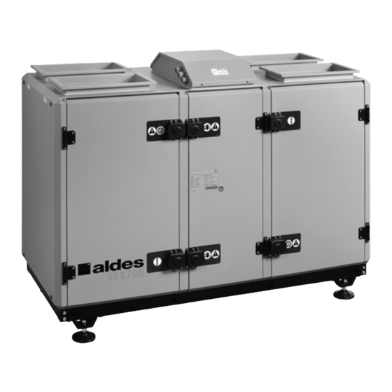
- Page 1 720T / 725T / 740T / Assembly & Maintenance Guide 750T / 760T / 770T / 780T / 790T www.aldes.com...
-
Page 2: Table Of Contents
TABLE OF CONTENTS 1. Recommendations and safety setpoints........................3 2. Check List ..................................4 3. Unit Components................................5 4. Unit Confi guration ................................6 5. Dimensions ...................................7 6. Installation ..................................8 7. Electrical Connection ..............................11 8. Selection of Electrical Cable Cross-Section ......................13 9. Maintenance ................................14 10. -
Page 3: Recommendations And Safety Setpoints
1. RECOMMENDATIONS AND SAFETY SETPOINTS • This unit has to be used under proper conditions according to its technical specifi cation and design purpose. (Otherwise responsibility belongs to practitioner) • Unauthorized personnel must not interfere in unit and/or must not use unoriginal spare parts. (Otherwise responsibility of failure that may occur belongs to practitioner) •... -
Page 4: Check List
2. CHECK LIST In the event of unit failure and pre-commissioning checks to be made are determined as follows; after checking this information, please contact our company in case failure continues. Controls √ Make sure that the unit receives power and electrical grounding is made! Make sure that the electricity cables are drawn from in the correct cross section! (Please check whether there is heating on cables or not.) Please check whether the cables in unit control panel are shielded (shielded magnetic... -
Page 5: Unit Components
3. UNIT COMPONENTS VEX700T Series Units Rotary energy recovery Control Duct connections Exhaust and supply air fans Pre-filter (Optional) Exhaust and supply air filters... -
Page 6: Unit Confi Guration
4. UNIT CONFIGURATION VEX700T Series Units Right-Hand Type Left-Hand Type... -
Page 7: Dimensions
5. DIMENSIONS VEX700T Series Units One-section version Two-section version *Side view *Front view *Front view The M quotation represents the space requiered for the maintenance of the unit (substitution of fans, fi lters...).The S quotation represents the space requiered to change the heat exchanger. -
Page 8: Installation
6. INSTALLATION Disassembly of bi-blocs VEX700T Units The following information is available for Multi-blocs VEX750T/760T/770t/780T/790T series. Figure-1 Figure-1-1 - Remove the rain protection cover which is assembled on the unit. - Unscrew the bolts of connecting parts of the blocs. (Figure-1-3) - Unscrew the bolts of connecting parts of the bloc base frame. - Page 9 The following information is available for Multi-blocs VEX750T/760T/770T/780T/790T series. Figure-3 - Prepare the installation parts. - Remove shipping bolts on the mounting surface. - Assemble the contact surfaces of the unit with the help of sealing as shown in Figure 3. - Check the seals in between the blocs.
- Page 10 Lifting Considerations - Do not lift the unit when it is windy and while a personnel is working under the unit. - Use lifting chain as shown below. Lifting chains must be capable of supporting the entire weight of the device. - Lifting chains may not be the same length.
-
Page 11: Electrical Connection
7. ELECTRICAL CONNECTION System Connections 1- Cut the gaskets in cable connection hole from the center. 2- Pass the on/off switch cables through the cable connection hole. 3- Connect the main power cable and ground wires to the terminals in the junction box. 4- Use cable tie to hold the cables tightly. - Page 12 Electrical connection This electrical diagram is a general document. Please refer to the electrical diagram located on the unit. Extract Air Pressure Flow Cooling Battery Control 0-10V Supply Air Pressure Flow Sensor 0-10V Outdoor Temperature Sensor Supply Temperature Sensor Extract Temperature Sensor 0-10V Heater Battery Control Filter Guard...
-
Page 13: Selection Of Electrical Cable Cross-Section
8. SELECTION OF ELECTRICAL CABLE CROSS-SECTION Electrical Cable Selection of Energy Recovery Unit - 400V 3 phase + Neutral + ground Unit Model Power Current Fuse (kW) 720T 3 x 3 725T 3 x 3 740T 3 x 4 750T 3 x 6 760T 3 x 10... -
Page 14: Maintenance
9. MAINTENANCE Filter Maintenance To clean up G class fi lters; To clean up F / M class fi lters: - Turn off the unit. - Turn off the unit. - Remove dirty fi lters. - Remove dirty fi lters. - Use a vacuum cleaner to clean the dust from the air fi lter. - Page 15 Maintenance Period Every year: - Check tension of the drive belt and be sure the belt is running properly (for units with rotary type heat exchanger) - Paint the exterior surface of casing to prevent corrosion on metal surfaces of the unit. - Clean fan propeller and fan shaft of the fan.
-
Page 16: Pressostat - Installation And Operating Instructions
10. PRESSOSTAT - INSTALLATION AND OPERATING INSTRUCTIONS 2-9/16 2-17/64 [65] [57.5] 1-31/32 Ø11/64 [50] [22] [Ø4.5] 21/64 [8.5] 2-21/64 [59] 19/64 Ø15/64 [7.5] [Ø6] 51/64 [18] (P2) (P1) The Series aDpS adjustable Differential pressure Switch is de- SPECIFICATIONS signed for overpressure, vacuum, and differential pressure applica- Service: Air and noncombustible, compatible gases. - Page 17 Electrical connection Setting the pressure Range Work on electrical installations must only be carried out by electri- Make absolutely certain that there is no voltage on the electrical con- cians who are specifi cally trained for this purpose. nections before you carry out any setting on the pressure switch. Otherwise, it could be fatal if you accidentally touch the electrical First make sure that there is no voltage on the connections or the metal adjusting screw while you are performing...
- Page 18 11. DIFFERENTIAL PRESSURE TRANSMITTER ® MAGNESENSE II DIFFERENTIAL PRESSURE TRANSMITTER Monitors Pressure, Air Velocity and Air Flow, BACnet/Modbus ® Communications 21/32 Ø3-7/16 21/32 29/32 [16.67] [Ø87.31] [16.67] 2-11/64 [23.02] [55.17] [12.70] 2-41/64 [67.07] 2-9/16 57/64 1/2 NPS [65.09] [22.62] Wall Mount Bracket (3) 3/16 [4.76] HOLES EQUALLY SPACED ON A 4.115 [104.52] BC...
- Page 19 Model chart Model in w.c. mm w.c. MS2-W101 0.10, 0.15, 0.25, 0.50 25, 40, 50, 125 2.5, 4, 6, 10 0.025, 0.04, 0.05, 0.125 ±0.10, ±0.15, ±0.25, ±0.025, ±0.04, ±0.05, MS2-W111 ±25, ±40, ±50, ±125 ±2.5, ±4, ±6, ±10 ±0.50 ±0.125 1, 2, 3, 5 250, 500, 750, 1250...
- Page 20 www.aldes.com...
Need help?
Do you have a question about the VEX 720T and is the answer not in the manual?
Questions and answers