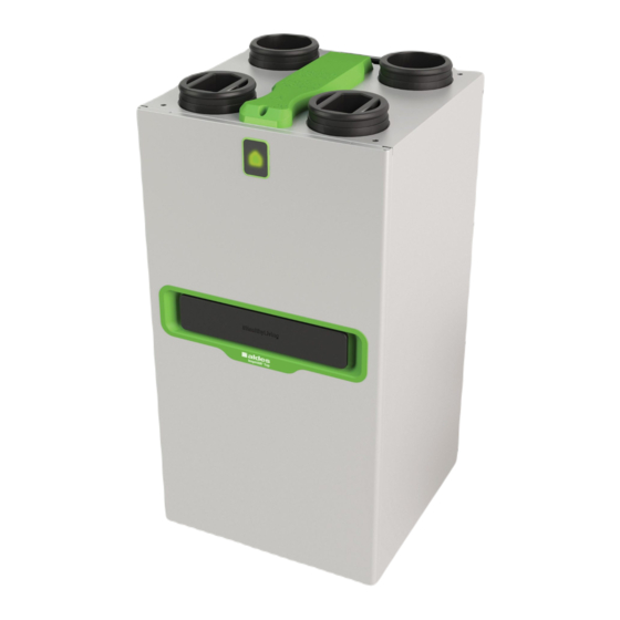
aldes InspirAIR Top Manual
Heat recovery ventilation for single-family dwelling
Hide thumbs
Also See for InspirAIR Top:
- Assembly instructions manual (100 pages) ,
- User manual (28 pages) ,
- Installation instructions manual (28 pages)
Table of Contents
Advertisement
Quick Links
Advertisement
Table of Contents

Related Manuals for aldes InspirAIR Top


Summary of Contents for aldes InspirAIR Top
- Page 1 Heat recovery ventilation Heat recovery ventilation ® InspirAIR Heat recovery ventilation for single-family dwelling Description Intervention Exploded views and Parts Electrical wiring diagrams guide Maintenance instructions Repair guide Version 1.0 – 03/2021 Page 1 of 31...
-
Page 2: Table Of Contents
Contents General information ............................3 Reference documents and related tools ..................... 3 General description ............................4 InspirAIR ® Top Heat Recovery Ventilation System ..................4 Typical example of installation ........................4 Product and kit references .......................... 4 Differences between Classic and Premium ....................5 Dimensions .............................. -
Page 3: General Information
It is mandatory to use a Modbus RS485 to USB cable. Aldes sells this cable under the reference 11023320 - INSPIRAIR USB CONNECTION CABLE RS485 1.8 M. A complete package of videos are available online to present the unit and train installer for the installation, the settings and the maintenance of our new range InspirAIR®... -
Page 4: General Description
*The kits exclusive to the French market include the unit only (11023473 or 11023475), the InspirAIR® remote control 11023479 and the condensate kit 11023483. The unit must be connected permanently to a remote control to operate. The unit can be commissioned with the remote control or Aldes Configurator Page 4 of 31... -
Page 5: Differences Between Classic And Premium
Different heat exchanger in the CLASSIC ▪ No light signal on front panel for the with less pressure drops but less thermal CLASSIC efficiency ▪ No Aldes Connect Box as standard for the ▪ Filtration level higher on PREMIUM Classic ® InspirAIR TOP Classic InspirAIR ®... -
Page 6: Exploded View And Parts List
3. Exploded view and parts list 3.1 Exploded view (Version 300/450/VEX40T Classic) Page 6 of 31... -
Page 7: Exploded View (Version 300/450/Vex40T Premium)
3.2 Exploded view (Version 300/450/VEX40T Premium) Page 7 of 31... -
Page 8: Spare Parts List
3.3 Spare parts list Reference Description Reference InspirAIR® Top electronic board 11101400 InspirAIR® Top 300 right-motor kit 11101407 InspirAIR® Top 450 S/E right-motor kit 11101409 InspirAIR® Top 300 S/E left-motor kit 11101408 InspirAIR® Top 450 S/E left-motor kit 11101410 InspirAIR® Top 300/450 Classic heat exchanger 11101411 InspirAIR®... -
Page 9: Options & Accessories
3.4 Options & Accessories Filters: please refer to the user manual or the Aldes website Enter Product Description Item Walter® connected sensor 11023470 InspirAIR® CO2 remote control 11023480 InspirAIR® remote control 11023479 AldesConnect Box® 11023386 CO2 sensor 11017090 Power supply 230/24 V for CO2 sensor... -
Page 10: Electrical Wiring Diagrams
0-10 V Temperature sensors Sensor service Fan Status Input 0-10 V General Internal Customer Installer Kitchen button supply preheating MODBUS keypad port Aldes Ibus coil *Pressure plug available only on "InspirAIR Top pressure kit" electronic board Page 10 of 31... -
Page 11: Inspirair® Remote Control Menus
5. InspirAIR® remote control menus INFORMATION The INFORMATION menu can be accessed without password. It display the unit's key settings without being able to alter them. Menu Sub-menu Settings Regulation In progress Comfort temperature Filters Filter status Number days remaining Error Product ID Product number... - Page 12 INSTALLER (code 0405) The INSTALLER menu is specific for a competent installer and can be accessed with the password: 0405. The installer can access all the settings, accessories and operating and maintenance data for the machine. Menu Sub-menu Commissioning reboot Settings Country, language Date and time...
-
Page 13: Control
6. Control 6.1 Bypass Priority given to heating mode By-pass open Heat exchanger mode Bypass closed T° incoming stale air on heat exchanger (°C) Priority given to cooling mode* Heat exchanger mode Bypass closed By-pass open * The T°C of the fresh air (coming from outside) is lower than the T°C... -
Page 14: Frost Protection
/!\ bypass not used in the frost protection function * The "PassivHaus" or "Not PassivHaus" certification mode can be configured in Aldes Configurator in the InspirAIR remote control in this menu: Installer > Settings > Certifications The unit is factory configured as "Not PassivHaus*"... -
Page 15: Maintenance Instructions
➔ USB key to recover history and updates ➔ Standard tools ➔ Modbus RS485 to USB cable for use of Aldes Configurator ➔ Unit and remote control software programs up-to-date if updating is possible* *Up-to-date versions of both these software programs along with an "end user" procedure for updating the software are available here in French and English: https//inspirair-top-software.aldes.com... -
Page 16: List Of Inspirair ® Top Preventive Maintenance Operations
7.1 List of InspirAIR ® Top preventive maintenance operations P-101 P-201 Replacement Cleaning of filters of heat exchanger Frequency: Frequency: Nbr.: every six to Heat Nbr.: Filters 5 min every 3(+) twelve exchanger years months List of steps: List of steps: - Step 1, 4 - Step 1, 2, 10, 11 7.2 List of InspirAIR... - Page 17 C-205 C-206 Replacement Reflash the electronic of sensors board from the unit Standard tools Nbr.: Standard Core 30 min and USB key + tools software List of steps: List of steps: - Step 1, 2, 3, 7, 9 - Step 12 C-207 HMI reflasher Nbr.:...
-
Page 18: Inspirair ® Top Operating Procedures
7.3 InspirAIR Top operating procedures ® Step 1 Switch the unit off - Power off the unit using the electrical cabinet circuit breaker operated by an accredited person. Step 2 Open the door - Remove the filter plugs - Remove the two door fastening screws Step 3 Open upper box... - Page 19 Step 4 Change the filters - Open the access hatch to the filters - Remove the filters - Insert the new filters - Watch out for the fitting direction for the pollen filters: the arrow must point in the same direction as the one on the box fan Page 19 of 31...
- Page 20 Step No. 5 Change the left motor - Unplug the left motor connectors - Remove the left motor cover by sliding the tool supplied with the motor to the centre on right for leverage. - Remove the "cable gland" foam (do not lose it) - Remove the air sensor from the volute...
- Page 21 Step 6 Change the right motor Unplug right motor connectors - Remove the right motor cover by sliding the tool supplied with the motor to the centre on left for leverage. - Remove the "cable gland" foam (do not lose it) - Remove the air sensor from the volute - Withdraw the motor cables...
- Page 22 Step 7 Replace the electronic board - Unplug all connectors from the board - Remove the three fastening screws - Slide the electronic box out of its housing. - Remove the four fastening screws - Disconnect all connectors. - Remove the four fastening screws Description Code...
- Page 23 Step 8 Replace the bypass - Unplug the bypass connector Withdraw the cable from the channel - Open bypass motor box - Remove the motor fastening screws - Unclip the flap ratchet - Remove the motor box - Withdraw the bypass flap Page 23 of 31...
- Page 24 Step 9 Change the sensor cables - Unplug the sensor connector from the electronic board - Remove the motor covers by using the tool supplied with the motor at the centre for leverage. - Remove the two sensors placed on the motors - Remove the two sensors above the filters (do not lose the foam plugs)
- Page 25 Step No. 11 Clean the heat exchanger - Remove the impurities in the heat exchanger (cleaning with air advised) Step No. 12 Flash the control board with new software - Power off the unit using the electrical cabinet circuit breaker operated by an accredited person.
-
Page 26: Repair Guide
7.4 Repair guide Please refer to the relevant user manuals for handling the user keypad or control core. Code to access Expert level on the control core: 0405 List of error codes: Code Meaning Solution No product ID Fill in product ID Check that the product has been configured (at least type of control Product not configured and R/L chosen) -
Page 27: Breakdown Flow Charts
7.5 Breakdown flow charts Page 27 of 31... - Page 28 Page 28 of 31...
- Page 29 Page 29 of 31...
- Page 30 Page 30 of 31...
- Page 31 Page 31 of 31...
Need help?
Do you have a question about the InspirAIR Top and is the answer not in the manual?
Questions and answers