Table of Contents
Advertisement
Quick Links
Advertisement
Table of Contents

Related Manuals for Burkert 8685


Summary of Contents for Burkert 8685
- Page 1 Type 8685 / 8686 Feedback Head / Control Head Robolux Operating Instructions...
- Page 2 We reserve the right to make technical changes without notice. Technische Änderungen vorbehalten. Sous réserve de modifications techniques. © Bürkert Werke GmbH & Co. KG, 2011 - 2018 Operating Instructions 1810/04_EU-EN_00809600 / Original DE...
-
Page 3: Table Of Contents
1 OPERATING INSTRUCTIONS ..............5 7 ASSEMBLY ....................14 Symbols ..................5 Safety instructions ..............14 Definition of term ..............5 Assembly of Type 8685 and Type 8686 on the actuator Type 2036..............14 2 AUTHORIZED USE ..................6 8 PNEUMATIC INSTALLATION ............... 19 Restrictions ................. 6 Safety instructions .............. - Page 4 Type 8685 / 8686 14 SHUTDOWN ....................42 14.1 Safety instructions ..............42 14.2 Disassembly................42 15 ACCESSORIES ................... 44 16 TRANSPORT, STORAGE, PACKAGING .......... 44 English...
-
Page 5: Operating Instructions
Designates a procedure which you must carry out. WARNING! 1.2 Definition of term Warns of a potentially dangerous situation. The term “device” used in these instructions always stands for the ▶ Failure to observe the warning may result in serious injuries or feedback head Type 8685 and control head Type 8686. death. English... -
Page 6: Authorized Use
Type 8685 / 8686 Authorizeduse AUTHORIZED USE BASIC SAFETY INSTRUCTIONS These safety instructions do not make allowance for any Non-intended use of the feedback head Type 8685 and the control head Type 8686 may be a hazard to people, nearby • contingencies and events which may arise during the assembly, equipment and the environment. operation and maintenance of the devices. The device is designed to be mounted on pneumatic actuators of •... - Page 7 NOTE! To prevent injuries: Electrostatic sensitive components/modules. ▶ The feedback head Type 8685 and control head Type 8686 must The device contains electronic components, which react sensitively not be used in areas where there is a risk of explosion. to electrostatic discharge (ESD). Contact with electrostatically ▶...
-
Page 8: General Information
Tel. + 49 (0) 7940 - 10 91 111 5.2 General description Fax + 49 (0) 7940 - 10 91 448 The feedback head Type 8685 and the control head Type 8686 are E-mail: info@burkert.com designed exclusively for integrated mounting on an actuator of the International diaphragm valve Type 2036 in sizes RV50, RV70, RV110. -
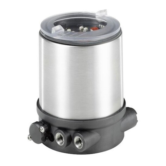
Page 9: Structure Of Feedback Head Type 8685
M12 x 1 Dummy plug M16 x 1.5 Fig. 1: Structure of feedback head Type 8685 Pressure limiting valve Electrical connection (for protection against too Cable gland M12 x 1.5 high internal pressure in... -
Page 10: Structure Of Adapter Set For Actuator Type 2036
Structure of adapter set for TECHNICAL DATA actuator Type 2036 6.1 Conformity The feedback head Type 8685 and the control head Type 8686 comply with EU directives in accordance with the EU Declaration of Conformity. 6.2 Standards The applied standards, which verify conformity with the EU Direc- tives, can be found on the EU Type Examination Certificate and / or the EU Declaration of Conformity. -
Page 11: Mechanical Data
Type 8685 / 8686 Technicaldata 6.4 Mechanical data 6.6 Pneumatic data Dimensions See data sheet Control medium neutral gases, air Quality classes in accordance with Body material PPS, PC, VA ISO 8573-1 Sealing material outside EPDM Dust content Class 7 Max. particle size 40 µm, inside NBR max. -
Page 12: Electrical Data For Feedback Head Type 8685
Type 8685 / 8686 Technicaldata 6.7 Electrical data for feedback head 6.7.2 Electrical data with AS-Interface bus control Type 8685 6.7.1 Electrical data without bus control Connections Remote 975 mm AS-Interface cable 24 V DC with circular plug-in connector (M12 x 1, 4-pole) Supply voltage 29.5 V – 31.6 V DC Connections Cable gland M12 x 1.5, wrench size 15 (according to specification) (clamping area 3 –... -
Page 13: Electrical Data Control Head Type 8686
Type 8685 / 8686 Technicaldata 6.8 Electrical data 6.8.2 Electrical data with AS-Interface bus control control head Type 8686 6.8.1 Electrical data without bus control Connections Remote 975 mm AS-Interface cable 24 V DC with circular plug-in connector (M12 x 1, 4-pole) Connections Cable gland M12 x 1.5, wrench size 15 (clamping area 3 – 6.5 mm) with screw terminals Supply voltage 29.5 V –... -
Page 14: Assembly
Type 8685 / 8686 Assembly ASSEMBLY 7.2 Assembly of Type 8685 and Type 8686 on the actuator Type 2036 7.1 Safety instructions An adapter set is required for assembly on the actuator Type 2036. The adapter set (see “Fig. 3”, page 10) includes an adaptation body, DANGER! a form seal, three O-rings, four cylinder screws and three switch spindle pairs. - Page 15 Type 8685 / 8686 Assembly NOTE! Designation Order no. Using a switch spindle that does not fit will result in irrepa- Adapter set for Type 8685 684267 rable destruction of the feedback head and/or control head Adapter set for Type 8686 684268 and the actuator. Tab. 2: Adapter sets ▶ Use only switch spindles that match the actuator size. The cor- responding actuator size identification (RV50, RV70, RV110)
- Page 16 The outside lead-throughs are designed for actuator For electrical installation see: “9.2 Device version 24 V DC” size RV70/110, while the inside lead-throughs for actuator size “Device connection for cable gland Type 8685” RV50 (see “Fig. 7”). “Device connection for cable gland Type 8686”...
- Page 17 Type 8685 / 8686 Assembly Mounting hole of the feedback head / control Recess head concentric with square nut of the adap- Switch spindle tation body O-ring 3.5 x 1.5 Type 8686 Type 8685 Fastening screw M4 Dummy plug Fig. 10: Fastening of feedback head / control head...
- Page 18 Type 8685 / 8686 Assembly Control head Type 8686 only: NOTE! Damage or malfunction due to ingress of dirt and moisture. Step 3: Assembly of pneumatic connection - install the actuator → ▶ To comply with degree of protection IP65 / IP67, install an Screw the plug-in hose connectors onto the control head and the exhaust air line on the unneeded pilot air port (for CFA, NC and actuator.
-
Page 19: Pneumatic Installation
Type 8685 / 8686 Pneumaticinstallation PNEUMATIC INSTALLATION Type 2036 Actuator 1 Actuator 2 The dimensions of the feedback head / control head and the different Connection Connection complete device models, consisting of control, feedback head / control D11, D55 head, actuator and valve, can be found in the relevant data sheets. -
Page 20: Pneumatic Installation Of Feedback Head Type 8685
Type 8685 / 8686 Pneumaticinstallation 8.2 Pneumatic installation of Important information for the problem-free functioning of feedback head Type 8685 the device: ▶ The installation must not cause back pressure to build up. The feedback head does not require a pilot air supply. ▶ To make the connection, select a hose with sufficient cross section. -
Page 21: Electrical Installation
Risk of injury from unintentional activation of the system and Screw terminals uncontrolled restart. ▶ Secure system from unintentional activation. Fig. 14: Position of screw terminals Type 8685 ▶ Following installation, ensure a controlled restart. → Loosen the fastening screws M4 and pull the feedback head up (only if the feedback head is already installed). - Page 22 Pilot air port Pilot air port Top2 2 (P2) 4 (P4) Bot2 Pilot air port Pilot air port Fig. 15: Designation on PCB Type 8685 1 (P1) 3 (P3) Designation Assignment on PCB 24 V Supply voltage + 24 V DC ±10% Fig.
- Page 23 Type 8685 / 8686 Electricalinstallation NOTE! NOTE! Faulty detection of end positions. If the torque is too high when screwing in the fastening screw or if the O-ring is missing, degree of protection IP65 / IP67 is ▶ For actuators with control function B (CFB, NO), the lower end not ensured. position must be approached before the feedback head is placed on the adaptation body. To do this, pressurize the appropriate pilot ▶...
- Page 24 Type 8685 / 8686 Electricalinstallation 9.2.2 Electrical installation of control head When the supply voltage is applied, the control head is operating. → Type 8686 Before the device can be used, the basic settings (see section “10.3.1 Basic settings”) must still be made on the control head.
- Page 25 Type 8685 / 8686 Electricalinstallation → Device connection for cable gland Type 8686 Guide the cables through the cable gland. → → Use a cable cross-section of 0.25 mm² for the electrical connection. Connect the wires (see pin assignment in “Tab. 6”). Designation Assignment External circuit on PCB Bottom end position - 24 V / 0 V (max.
- Page 26 Type 8685 / 8686 Electricalinstallation → Place the control head on the actuator. As you do, note: NOTE! - The dummy plug or pressure-relief valve must be located on the Malfunction due to damaged wires. side of the pneumatic connections of the actuator. ▶ To keep the spindle guides free, guide all wires through the - The caps must be in the starting position.
-
Page 27: Device Version As-Interface
Type 8685 / 8686 Electricalinstallation 9.3 Device version AS-Interface Wiring diagram of circular plug M12 The view shows the image from the front looking at the pins, the solder connections are behind them. 9.3.1 Electrical installation feedback head and control head Pin 3: Pin 4: The feedback head and control head are electrically connected by a Bus –... - Page 28 (data) and energy (power Extended ID code 1 7 hex supply voltage for the actuators and sensors) are transmitted. Extended ID code 2 E hex Profile S-0.A.E Tab. 8: Programming data for feedback head Type 8685 English...
- Page 29 Pilot air port Pilot air port not used 1 (P1) 3 (P3) not used Tab. 9: Bit configuration of AS-Interface for feedback head Type 8685 Parameter bits have no function. Fig. 23: Pneumatic connection Actuator assignment see “Fig. 23”. English...
- Page 30 Type 8685 / 8686 Electricalinstallation Bit configuration 9.3.5 LED status display for AS-Interface Data bit Status LED 1 Status LED 2 Function Assignment Inputs (green) (red) Top end position - 0 Top not reached Top actuator 1 1 Top reached POWER OFF Bottom end position - 0 Bot not reached...
-
Page 31: Control And Display
Type 8685 / 8686 Controlanddisplay CONTROL AND DISPLAY Slide switch Slide switch Color selection of end position Color selection of end position Actuator 1 Actuator 2 10.1 Control and display elements for LEDs feedback head Type 8685 LEDs Status of actuator 2 Status of actuator 1 (end position) (end position) 10.1.1 Device version 24 V DC... - Page 32 Type 8685 / 8686 Controlanddisplay 10.1.2 Device version AS-Interface LEDs AS Interface bus status Other than the AS-Interface bus status, the items listed below are designed separately for actuator 1 and 2. Slide switch for Slide switch for color selection of end position...
-
Page 33: Control And Display Elements For Control Head Type 8686
Type 8685 / 8686 Controlanddisplay 10.2 Control and display elements for LED status of pilot valve LED status of pilot valve control head Type 8686 Actuator 1 Actuator 2 Slide switch Slide switch The items listed below are designed separately for actuator 1 and 2. (service switch) -
Page 34: 10.3 Control
Type 8686 10.3.1 Basic settings Type 8685 To ensure the function of Types 8685 and 8686, these basic set- tings must be made before start-up in the isolated state. RV110 DANGER! - Page 35 Type 8685 / 8686 Controlanddisplay Step 3: Reference movement for spindle adjustment Typ 8686 To make the fine adjustment of the spindle for actuator size, it is essential Typ 8685 gn ye to move both spindles from the lower to the top end position.
- Page 36 Type 8685 / 8686 Controlanddisplay → Procedure for Type 8686: Close the transparent cap / body casing (auxiliary tool for → installing the cover: 674077 Under maximum control pressure, switch the service switch to “On”. The spindle moves to the upper end position.
- Page 37 Type 8685 / 8686 Controlanddisplay 10.3.2 Changing the settings 10.3.3 Manual activation of pilot valves with the control head Type 8686 Procedure: → The pilot valves can be switched with the service switches. With Unscrewing the transparent cap makes the slide switches and DIP control function A, the spindle moves up with switch position switches accessible.
- Page 38 Type 8685 / 8686 Controlanddisplay → Close the transparent cap (auxiliary tool for installing the cover: NOTE! 674077 Damage or malfunction due to ingress of dirt and moisture. ▶ To comply with degree of protection IP65 / IP67, screw in the transparent cap / body casing all the way.
-
Page 39: Safety Positions
Type 8685 / 8686 Safetypositions SAFETY POSITIONS MAINTENANCE Safety positions after failure of the electrical or pneumatic auxiliary 12.1 Safety instructions power: DANGER! Safety positions after failure Actuator of the auxiliary power Designation Risk of injury from high pressure in the equipment/device. type electrical pneumatic ▶ Before working on equipment or device, switch off the pressure and deaerate/drain lines. -
Page 40: 12.2 Service At The Air Intake Filter
Type 8685 / 8686 Maintenance 12.2 Service at the air intake filter Procedure: → Unlock the quick connector by pressing the holding element and DANGER! pulling out the air intake filter (if necessary, use a suitable tool in between the recesses in the head of the filter). -
Page 41: Malfunctions
Type 8685 / 8686 Malfunctions MALFUNCTIONS Malfunction Cause and remedial action Faulty detection Wrong actuator size selected with the DIP Malfunction Cause and remedial action of end position switches End position is No or inadequate supply voltage → Select the matching actuator size → not detected... - Page 42 Type 8685 / 8686 Malfunctions WARNING! Malfunction Cause and remedial action Risk of injury from improper removal. AS-Interface No or inadequate supply voltage ▶ Removal may be carried out by authorized technicians only and → bus status Check contact of ribbon cable terminal with with the appropriate tools.
- Page 43 Type 8685 / 8686 Malfunctions 2. Electrical connection Control head Type 8686 DANGER! Electrical Risk of electric shock. connection ▶ Before working on equipment or device, switch off the power Fastening supply and secure to prevent reactivation. screw (2x) ▶ Observe applicable accident prevention and safety regulations for electrical equipment.
- Page 44 Type 8685 / 8686 Accessories ACCESSORIES TRANSPORT, STORAGE, PACKAGING Designation Order no. NOTE! Connecting cable M12 x 1, 8-pole 919061 Transport damage. Auxiliary tool for installing the transparent cap 674077 Inadequately protected equipment may be damaged during transportation. Tab. 17: Accessories ▶ During transportation protect the device against moisture and dirt in shock-resistant packaging.
- Page 46 www.burkert.com...
Need help?
Do you have a question about the 8685 and is the answer not in the manual?
Questions and answers