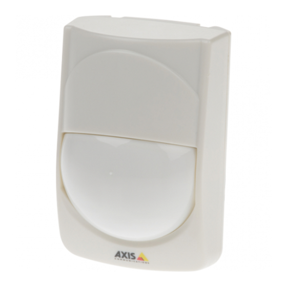
Summary of Contents for Axis T8331 series
- Page 1 01304 827609 AXIS T8331 PIR Motion Detector Series User Manual...
- Page 2 About this Document Contact Information Axis Communications AB This manual is intended for administrators and users of AXIS T8331 PIR Emdalavägen 14 Motion Detector Series. It includes instructions for using and managing 223 69 Lund the product on your network. Later versions of this document will be Sweden posted at www.axis.com...
-
Page 3: Table Of Contents
Hardware Overview ..........AXIS T8331 PIR Motion Detector Series Graphs ..... . . -
Page 4: Functions
Set the Pulse count switch to TEST. • Set the LED switch to ON (default setting). This applies to AXIS T8331 only. After the warmup period is completed (approximately 60 s), conduct a walk test by moving in the detection zone of the PIR sensor. -
Page 5: Masking Strips
Below text applies to AXIS T8331 only. For AXIS T8331 it is possible to set the LED switch to OFF/ON. By default the switch is set to ON. When in this mode the LED will lit when triggered. When set to OFF the LED will not be lit when triggered. -
Page 6: Sensitivity Switch
VMD and PIR AXIS Video Motion Detection (VMD) is an application for Axis camera products. VMD can be used together with the PIR sensor. The application detects moving objects within a predefined area of interest, making it possible to automatically trigger an event. - Page 7 The VMD detection area and the PIR sensors detection pattern are not synchronized by default. VMD detection area can be set in a user interface. The detection pattern for AXIS T8331–E can be modified by using the supplied masking strips.
-
Page 8: Reference Material
AXIS T8331 PIR Motion Detector Series Reference Material Reference Material Hardware Overview AXIS T8331 I/O interface Terminals PIR sensor (do not touch) Sensitivity switch Tamper switch LED switch AXIS T8331–E... -
Page 9: Axis T8331 Pir Motion Detector Series Graphs
AXIS T8331 PIR Motion Detector Series Reference Material Day/Night mode adjustment Mirror Photocell Detection area adjustment screw I/O interface Pulse count switch Tamper switch PIR sensor (do not touch) 10 Sensitivity switch 11 Terminals AXIS T8331 PIR Motion Detector Series Graphs AXIS T8331 graph... -
Page 10: Axis T8331 Pir Motion Detector Series Terminal Connections
AXIS T8331 PIR Motion Detector Series Terminal Connections AXIS T8331 Below are images of the terminal connection for AXIS T8331. The left image shows the default connection with tamper and alarm together. The right image shows a connection with tamper and alarm separated. This connection requires a camera with at least two configurable I/O ports. -
Page 11: Axis T8331 Pir Motion Detector Series Schematics
For position of the terminals, see Hardware Overview on page 8 AXIS T8331 PIR Motion Detector Series Schematics Below is a schematic showing the connection with a camera and the PIR sensor. This is the default connection with tamper and alarm together (Pin 3). - Page 12 I/O con gured as input I/O con gured as input Note • This connection requires a camera with at least two configurable I/O ports. • This connection requires changes in the terminal, see AXIS T8331 PIR Motion Detector Series Terminal Connections on page 10...
- Page 13 User Manual Ver. M1.13 AXIS T8331 PIR Motion Detector Series Date: November 2015 © Axis Communications AB, 2015 Part No. 1518265...


Need help?
Do you have a question about the T8331 series and is the answer not in the manual?
Questions and answers