Table of Contents
Advertisement
Advertisement
Table of Contents

Related Manuals for DFRobot FIREBEETLE BOARD-ESP32


Summary of Contents for DFRobot FIREBEETLE BOARD-ESP32
- Page 1 FIREBEETLE BOARD-ESP32 USER MANUAL V0.1...
-
Page 2: Table Of Contents
STEP1: The way to download Arduino IDE software................9 STEP2: Language setting of Arduino IDE ..................... 11 STEP3: Installation of the core center of the FireBeetle Board-ESP32 development board..11 STEP4: Connect FireBeetle Board-ESP32 to computer..............13 STEP5: Processing in the Arduino IDE.................... -
Page 3: Chapter1 Introduction
Introduction of FireBeetle FireBeetle has been translated to firefly in Chinese. It is a new product range that developed by DFRobot. The ultralow-power design of external hardware and small compatibility interface can fast build Internet of Things (IOT) conveniently. In simple terms, FireBeetle is an easy to use Internet of Things development platform. It is based on the theme of series of low-power hardware development and designed to work simple for intelligent hardware enthusiasts, interaction designers and electronic software engineers. -
Page 4: Introduction Of Firebeetle Board-Esp32
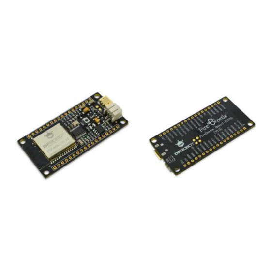
Caution: A lurry of FireBeetle products are still in development. Introduction of FireBeetle Board-ESP32 FireBeetle Board-ESP32 is one of the FireBeetle series and the chip of the master control board is ESP32. Aimed at Internet of Things, the SOC combines Wi-Fi, Bluetooth and MCU. The master control board uses ultra-low power consumption external hardware design (an actual measurement of the electricity current under low power consumption mode is 10 μA), supporting... - Page 5 Welcome to DFRobot: www.DFRobot.com.cn 5 / 49 IO3/RXD:D0(Arduino), the RX of Serial, connects to IO3 of ESP32 IO1/TXD:D1(Arduino), the TX of Serial, connects to IO1 of ESP32 IO25/D2:D2 (Arduino) of GPIO digital input and output port and PWM output pin, connect to IO25 of ESP32.
- Page 6 Welcome to DFRobot: www.DFRobot.com.cn 6 / 49 IO35/A3:A3 (Arduino), analog input, connect to IO35 of ESP32. IO15/A4:A4 (Arduino), analog input, connect to IO15 of ESP32. NC:Not connected IO0:Digital interface, connect to IO0 of ESP32. SCK:Clock pin of SPI, connect to IO18 of ESP32.
-
Page 7: Chapter2: Quick-Start
Welcome to DFRobot: www.DFRobot.com.cn 7 / 49 Chapter2: Quick-start FireBeetle Board-ESP32 Hardware In the Chapter1, we have introduced pins and corresponding peripheral default profiles of Arduino IDE. Please refer to the Chapter1 if you have any enquiry related to the special provision of pins. -
Page 8: Specification
On-board reset bottom Hardware vision: V1.0 FireBeetle Board-ESP32 can charged by lithium battery. The port as shown below. Specification FireBeetle Board-ESP32 mother board is fully compatible with FireBeetle range, the dimension parameters of it shown as below. -
Page 9: Arduino Ide For Firebeetle Board-Esp32
Arduino IDE for FireBeetle Board-ESP32 FireBeetle Board-ESP32 is easy for and on its users, even for a novice. The tutorial below present the way to download and install Arduino IDE software, processing in Arduino IDE. 3 Basic necessities: a FireBeetle Board-ESP32, USB data wire, and a computer that runs with Windows/Mac OS/Linux system and has network. - Page 10 Welcome to DFRobot: www.DFRobot.com.cn 10 / 49 Caution: as the tutorial used Arduino IDE 1.8.0, please use Arduino 1.8.0 or later ones for the best experience. Please choose the corresponding installation package from the list to the right of the download page.
-
Page 11: Step2: Language Setting Of Arduino Ide
Arduino IDE installation package does not contain the core center of the FireBeetle Board- ESP32.Therefore, we need to add it manually. To add FireBeetle Board-ESP32 we should add the core center of the FireBeetle Board-ESP32 firstly by hand in the Arduino development manager. - Page 12 Welcome to DFRobot: www.DFRobot.com.cn 12 / 49 Input FireBeetle and wait for the loading in the board manager. FireBeetle 0.03 is the right one. You can also choose the latest version and click Install. It will cost 5 to 10 minutes in average.
-
Page 13: Step4: Connect Firebeetle Board-Esp32 To Computer
When we installed the Arduino IDE and the core center of the FireBeetle Board-ESP32 successfully, FireBeetle Board-ESP32 can be connected to computer by USB data wire. If the operation is right, CHG power light of the FireBeetle Board-ESP32 will flash to check whether the lithium battery has been applied. - Page 14 Welcome to DFRobot: www.DFRobot.com.cn 14 / 49 If the device cannot be recognized, you should download FireBeetle Board-ESP32 driver to the computer. Download link: https://github.com/Chocho2017/FireBeetle-Board-ESP32.git Save the drive file FireBeetle-ESP32.inf to anywhere in your computer, right click on FireBeetle- ESP32...
-
Page 15: Step5: Processing In The Arduino Ide
Welcome to DFRobot: www.DFRobot.com.cn 15 / 49 Caution: FireBeetle-ESP32.inf file should be saved into the drivers’ file of Arduino IDE. And follow the prompts to fulfill the installation of drive file. STEP5: program in the Arduino IDE. After the installation of Arduino IDE software, operating it and open the processing window. In this window, you can edit and upload codes, and use the built-in serial monitor to the communication between serial and development board. -
Page 16: Step6: Upload Codes To Firebeetle-Esp32 Motherboard
Setup. STEP6: upload codes to FireBeetle-ESP32. In this step, an example process Blink of FireBeetle Board-ESP32 will be represented to you. Blink controls the LED light of D9 flash in every one second. Same as many Arduino boards, FireBeetle Board-ESP32 has a LED light, D9. Therefore, no other peripheral object is needed. LED’s status indicator can be found in the mother board of FireBeetle Board-ESP32. - Page 17 Tools->Board-> FireBeetle-ESP32. In general, this step performs only once on first use if you would not change the board. Switch to Tools->Port, according to the number of serial port shown in the FireBeetle Board-ESP32, we should choose COM3 as the communication port. The communication port appears only when the development board has connected to a computer and been successfully recognized.
- Page 18 Welcome to DFRobot: www.DFRobot.com.cn 18 / 49 Finally, clicking upload to burn the program onto the FireBeetle Board-ESP32. If you upload it successfully, message Done uploading would be presented in the information window. Meanwhile, D9 starts to flash.
- Page 19 Upload Above are primary methods of how to use FireBeetle Board-ESP32 in the Arduino IDE. Please feel free to our forum to contact us if you have any enquiry or suggestion. Caution: developers are the most common users of FireBeetle Board-ESP32 and not all peripherals have examples for reference, for there is some bugs to be discovered and repaired.
-
Page 20: Chapter 3: The Basics Of Using Peripherals In The Firebeetle Board-Esp32
Chapter 3: The Basics of Using Peripherals in the FireBeetle Board-ESP32 This chapter covers the basics of how to use peripherals in the FireBeetle Board-ESP32 by some example projects. You can also modify the example projects below to finish your own projects. - Page 21 Once you click Upload, IDE will send codes to FireBeetle Board-ESP32. Caution: please referring the previous tutorial if you forget the way to verify/compile/upload. The example is Ttem-1 of the file: Course.
-
Page 22: Project2: Pwm (Breathing Light)
Components in need 1 x FireBeetle Board-ESP32 Hardware linking method No need for other sensor, L LED light in the FireBeetle Board-ESP32 is available. Please connect FireBeetle Board-ESP32 directly to your computer by USB data wire. Enter code Open Arduino IDE. You would better enter the code manually than open Course->Item-2... - Page 23 Please click verify/compile to review and please upload it after the confirmation. Once you click Upload, IDE will send code to FireBeetle Board-ESP32. You can see the breath of LED light when you uploaded the codes. Let’s review the codes and hardware and check the way they work.
- Page 24 (LEDC_CHANNEL_0, LEDC_BASE_FREQ, LEDC_TIMER_13_BIT); ledcAttachPin (LED_PIN, LEDC_CHANNEL_0); The two codes are the setting functions of FireBeetle Board-ESP32 timer. We need to know how to use functions mentioned before to set timer. Please check base code if you are interested in the function prototypes (the link of base code: C:\Users\“your-PC”\AppData\Local\Arduino15\...
-
Page 25: Project3 Adc
ADC, an analog-to-digital converter, shorthand as A/D converter, can convert analog signal to digital signal. There are 12 bits of FireBeetle Board-ESP32 and its crest output value is 4095. There are 10 bits of Arduino UNO and its crest output value is 1023. In comparison, FireBeetle Board- ESP32 has higher precision, faster conversion rate than Arduino UNO. - Page 26 26 / 49 1 x FireBeetle Board-ESP32 Hardware linking method Plug FireBeetle Covers-Gravity Adapter Board to FireBeetle Board-ESP32 and plug simulative angle sensor into A0 here in the ADC experiment. And connect FireBeetle Board-ESP32 directly to your computer by USB data wire.
- Page 27 Caution: Please referring the previous tutorial if you forget the way to verify/compile/upload. Code analysis Because ADC of FireBeetle Board-ESP32 is fully compatible with Arduino analogRead function, no more explanation of analogRead function. Caution: If you are not familiar to the basics of Arduino function, please...
-
Page 28: Project4 I2C
28 / 49 Project4 I2C I2C of FireBeetle Board-ESP32 can be set to all I/O and allocated by uploading relative data. We have already set the default configuration to make it more convenient to use. It is fully compatible with Arduino. Look up the Chapter1, the introduction, the default pins. The project based on the default configuration of I2C to drive OLED display screen. - Page 29 1 x FireBeetle Board-ESP32 Hardware connection Plug FireBeetle Covers-Gravity Adapter Board to FireBeetle Board-ESP32 and plug Gravity I2C OLED-2864 Display Screen into I2C here in the I2C experiment, shown as below. Then connect FireBeetle Board-ESP32 directly to your computer by USB data wire.
- Page 30 Welcome to DFRobot: www.DFRobot.com.cn 30 / 49 With codes as follows #include <Wire.h> int UG2864Address = 0x3C;//OLED UG2864 7 bit address of the device unsigned char show2[] ={ 0x00,0x00,0x00,0x00,0x00,0x00,0x00,0x00,0x00,0x00,0x00,0x00,0x00,0x00,0x00,0x00,//*page0 0x00,0x00,0x00,0x00,0x00,0x00,0x00,0x00,0x00,0x00,0x00,0x00,0x00,0x00,0x00,0x00,// 0x08,0xF8,0x08,0x08,0x08,0x10,0xE0,0x00,0x08,0xF8,0x88,0x88,0xE8,0x08,0x00,0x00, //DF 0x08,0xF8,0x88,0x88,0x88,0x88,0x70,0x00,0x00,0x00,0x80,0x80,0x80,0x80,0x00,0x00,//Ro 0x08,0xF8,0x00,0x80,0x80,0x00,0x00,0x00,0x00,0x00,0x80,0x80,0x80,0x80,0x00,0x00,//bo 0x00,0x80,0x80,0xE0,0x80,0x80,0x00,0x00,0x00,0x00,0x00,0x00,0x00,0x00,0x00,0x00,//t 0x00,0x00,0x00,0x00,0x00,0x00,0x00,0x00,0x00,0x00,0x00,0x00,0x00,0x00,0x00,0x00,// 0x00,0x00,0x00,0x00,0x00,0x00,0x00,0x00,0x00,0x00,0x00,0x00,0x00,0x00,0x00,0x00,// 0x00,0x00,0x00,0x00,0x00,0x00,0x00,0x00,0x00,0x00,0x00,0x00,0x00,0x00,0x00,0x00,//*page1 0x00,0x00,0x00,0x00,0x00,0x00,0x00,0x00,0x00,0x00,0x00,0x00,0x00,0x00,0x00,0x00,// 0x20,0x3F,0x20,0x20,0x20,0x10,0x0F,0x00,0x20,0x3F,0x20,0x00,0x03,0x00,0x00,0x00,//DF...
- Page 31 Welcome to DFRobot: www.DFRobot.com.cn 31 / 49 0x00,0x00,0x00,0x00,0x00,0x00,0x00,0x00,0x00,0x00,0x00,0x00,0x00,0x00,0x00,0x00,//*page5 0x00,0x00,0x00,0x00,0x00,0x00,0x00,0x00,0x00,0x00,0x00,0x00,0x00,0x00,0x00,0x00,// 0x00,0x00,0x00,0x00,0x00,0x00,0x00,0x00,0x00,0x00,0x00,0x00,0x00,0x00,0x00,0x00,// 0x00,0x00,0x00,0x00,0x00,0x00,0x00,0x00,0x00,0x00,0x00,0x00,0x00,0x00,0x00,0x00,// 0x00,0x00,0x00,0x00,0x00,0x00,0x00,0x00,0x00,0x00,0x00,0x00,0x00,0x00,0x00,0x00,// 0x00,0x00,0x00,0x00,0x00,0x00,0x00,0x00,0x00,0x00,0x00,0x00,0x00,0x00,0x00,0x00,// 0x00,0x00,0x00,0x00,0x00,0x00,0x00,0x00,0x00,0x00,0x00,0x00,0x00,0x00,0x00,0x00,// 0x00,0x00,0x00,0x00,0x00,0x00,0x00,0x00,0x00,0x00,0x00,0x00,0x00,0x00,0x00,0x00,// 0x00,0x00,0x00,0x00,0x00,0x00,0x00,0x00,0x00,0x00,0x00,0x00,0x00,0x00,0x00,0x00,//*page6 0x00,0x00,0x00,0x00,0x00,0x00,0x00,0x00,0x00,0x00,0x00,0x00,0x00,0x00,0x00,0x00,// 0x00,0x00,0x00,0x00,0x00,0x00,0x00,0x00,0x00,0x00,0x00,0x00,0x00,0x00,0x00,0x00,// 0x00,0x00,0x00,0x80,0x80,0x80,0x00,0x00,0x80,0x80,0x00,0x80,0x80,0x80,0x00,0x00,//cn 0x00,0x00,0x00,0x00,0x00,0x00,0x00,0x00,0x00,0x00,0x00,0x00,0x00,0x00,0x00,0x00,// 0x00,0x00,0x00,0x00,0x00,0x00,0x00,0x00,0x00,0x00,0x00,0x00,0x00,0x00,0x00,0x00,// 0x00,0x00,0x00,0x00,0x00,0x00,0x00,0x00,0x00,0x00,0x00,0x00,0x00,0x00,0x00,0x00,// 0x00,0x00,0x00,0x00,0x00,0x00,0x00,0x00,0x00,0x00,0x00,0x00,0x00,0x00,0x00,0x00,// 0x00,0x00,0x00,0x00,0x00,0x00,0x00,0x00,0x00,0x00,0x00,0x00,0x00,0x00,0x00,0x00,//*page7 0x00,0x00,0x00,0x00,0x00,0x00,0x00,0x00,0x00,0x00,0x00,0x00,0x00,0x00,0x00,0x00,// 0x00,0x00,0x00,0x00,0x00,0x00,0x00,0x00,0x00,0x00,0x00,0x00,0x00,0x00,0x00,0x00,// 0x00,0x0E,0x11,0x20,0x20,0x20,0x11,0x00,0x20,0x3F,0x21,0x00,0x00,0x20,0x3F,0x20,//cn 0x00,0x00,0x00,0x00,0x00,0x00,0x00,0x00,0x00,0x00,0x00,0x00,0x00,0x00,0x00,0x00,// 0x00,0x00,0x00,0x00,0x00,0x00,0x00,0x00,0x00,0x00,0x00,0x00,0x00,0x00,0x00,0x00,// 0x00,0x00,0x00,0x00,0x00,0x00,0x00,0x00,0x00,0x00,0x00,0x00,0x00,0x00,0x00,0x00,// 0x00,0x00,0x00,0x00,0x00,0x00,0x00,0x00,0x00,0x00,0x00,0x00,0x00,0x00,0x00,0x00,// void Writec(unsigned char COM){ Wire.beginTransmission(UG2864Address); Wire.write(0x00); Wire.write(COM); Wire.endTransmission(); void Writed(unsigned char DATA){ Wire.beginTransmission(UG2864Address);...
- Page 32 Welcome to DFRobot: www.DFRobot.com.cn 32 / 49 Writec(0XA1);//set segment remap column address 127 is mapped to SEG0 Writec(0XA6);//normal / reverse normal display Writec(0XA8);//multiplex ratio Writec(0X3F);//1/64 Writec(0XC8);//Com scan direction remapped mode. Scan from COM[N-1] to COM0 Writec(0XD3);//set display offset Writec(0X00); Writec(0XD5);//set osc division Writec(0X80);...
- Page 33 Please click verify/compile to review and please upload it after the confirmation. Once you click Upload, IDE will send codes to FireBeetle Board-ESP32. Once the upload finishes, the Gravity I2C OLED-2864 Display Screen will show ‘DFRobot www.dfrobot.com.cn’, shown as below.
- Page 34 And the usage method of I2C is fully compliant with Arduino. void Writed(unsigned char DATA) Write data function. The usage method of I2C is fully compliant with Arduino. Caution: I2C of FireBeetle Board-ESP32 is fully compliant with Arduino, mainly by calling Wire files.
-
Page 35: Project5 Spi
SPI communication is widely used by sensors, for the higher rate than I2C and no address conflict. SPI, a communication bus of high speed, full-duplex, synchrony. SPI of FireBeetle Board-ESP32 can be allocated to all I/O. You can read underlying code to practice (not recommend to freshmen). - Page 36 Welcome to DFRobot: www.DFRobot.com.cn 36 / 49 1 x FireBeetle Board-ESP32 Enter code Open Arduino IDE. You would better enter the code manually than open Course-> Item-5 to be familiar with it. Sample code: #include <DFRobot_BME280.h> #define SEA_LEVEL_PRESSURE 1013.25f #define BME_CS D2 DFRobot_BME280 bme(BME_CS);...
- Page 37 IDE Please click verify/compile to review and please upload it after the confirmation. Once you click Upload, IDE will send codes to FireBeetle Board-ESP32. Once the upload finishes, open the built-in serial monitor of Arduino IDE, print message shown as below.
- Page 38 Code analysis The project mainly uses library file of BME280. Although there is no operation to the underlying of SPI, SPI of FireBeetle Board-ESP32 is fully compliant with Arduino. #define BME_CS D2 Different from Arduino, the setting of pin to SPI should transmit D2 not 2. What is more, D2, the SS dial switch of FireBeetle Covers-Gravity Adapter Board should be gated.
-
Page 39: Project6: Hall Sensor
39 / 49 Project6: Hall Sensor The hall sensor integrated by FireBeetle Board-ESP32 is based on N-carrier. Putting the chip into the electromagnetic field, a low voltage came into the resistance. The voltage not just can be directly collected and measured by ADC, but also can be measured by ADC after the amplification of the pre-analogue amplifier with super-low noise. - Page 40 Once you click Upload, IDE will send codes to FireBeetle Board-ESP32. Once the upload finishes, open the built-in serial monitor of Arduino IDE, print message shown as below. Caution: Change the distance of the magnet to FireBeetle Board-ESP32, you can see the variety of the printed numbers. Code analysis The hall sensor used in this project is integrated by FireBeetle Board-ESP32.
-
Page 41: Project7 Dac
41 / 49 Project7 DAC Opposite to ADC of Project3, DAC converts digital signal to analog signal. FireBeetle Board-ESP32 integrated two 8-bit DAC passing ways to convert two signals respectively. DAC circuit is composed of built-in series resistor and a buffer. Moreover, the two independent DAC can be used as both reference voltage and power supply for other circuits. - Page 42 Please click verify/compile to review and please upload it after the confirmation. Once you click Upload, IDE will send codes to FireBeetle Board-ESP32. Once the upload finishes, use an oscilloscope to test the voltage of D2, trapezium wave shown as below.
-
Page 43: Project8 Touch Sensor
43 / 49 Project8 Touch Sensor FireBeetle Board-ESP32 offers as many as 10 GPIO capacitance sensors. It can probe the difference of capacitance caused by the direct access or approach with hands or others. The characteristic of the low noise and high sensitivity works for relatively smaller touch board. It can be directly used to touch switch items. - Page 44 Once you click Upload, IDE will send codes to FireBeetle Board-ESP32. Once the upload finishes, open the built-in serial monitor of Arduino IDE, touch D9 with your hand (T2 corresponds to D9) print 1 shown as below.
-
Page 45: Project9 Deep_Sleep (Low Power Management)
If you want to recall the FireBeetle Board-ESP32 from power-down mode, external interrupt and RTC timer both take effects. The project explains the way to turn FireBeetle Board-ESP32 to power-down mode with Arduino code. Components in need 1 x FireBeetle Board-ESP32 Caution: No need for other sensor. - Page 46 ESP.deepSleep(5000000); void loop() { // put your main code here, to run repeatedly: Please click verify/compile to review and please upload it after the confirmation. Once you click Upload, IDE will send codes to FireBeetle Board-ESP32.
- Page 47 The parameter been passed is uint32_t type of data, value of time setting. The unit of it is μs (microsecond). In the sample program, let FireBeetle Board-ESP32 sleep and restart in 5 seconds, you can see LED light of the FireBeetle Board-ESP32 flash in every 5 seconds.
- Page 48 Please do not worry about its principle and underlying settings related, you just need to know how to use it. Allocable interruption pin and corresponding pins in the FireBeetle Board-ESP32 shown as below. The interrupt Parameter...
- Page 49 Welcome to DFRobot: www.DFRobot.com.cn 49 / 49...
Need help?
Do you have a question about the FIREBEETLE BOARD-ESP32 and is the answer not in the manual?
Questions and answers