Table of Contents
Advertisement
Quick Links
®
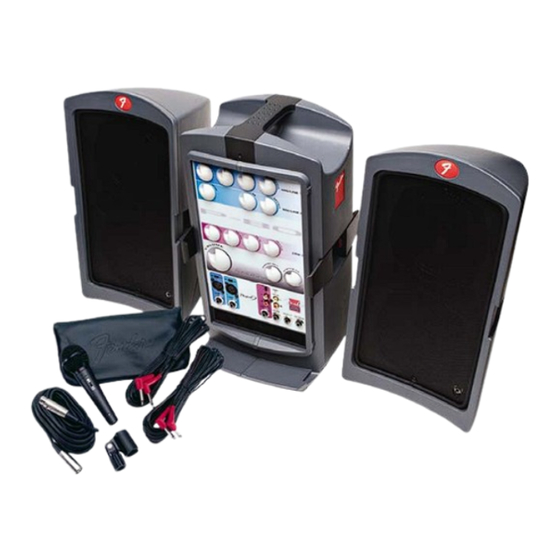
PASSPORT
P-80
(This is the model name for warranty claims)
p/n 069-1003-000
SERVICE MANUAL
ATTENTION:
WARRANTY SERVICE PROCEDURES
Warranty field service of the Passport® P-80 will be limited to replacement of defective
PCB Assemblies and all other parts not marked as "REF" in the Parts List. Non-Warranty
repairs can of course be to the component level at the Service Center's discretion. For
non-warranty component level repairs all parts listed as "REF" in the Parts List must be
sourced from suppliers other than FMIC.
Fender Musical Instruments Corporation, 8860 East Chaparral Road Suite 100 Scottsdale, AZ 85250
Issued: October, 2007
Advertisement
Table of Contents

Related Manuals for Fender PASSPORT P-80


Summary of Contents for Fender PASSPORT P-80
- Page 1 Service Center’s discretion. For non-warranty component level repairs all parts listed as “REF” in the Parts List must be sourced from suppliers other than FMIC. Fender Musical Instruments Corporation, 8860 East Chaparral Road Suite 100 Scottsdale, AZ 85250 Issued: October, 2007...
- Page 2 Fender® Musical Instruments Corporation. It is Corporation. not to be sold or assigned to another party and is disclosed solely for use by Fender Authorized • Parts marked with two asterisks ( Service Centers for purposes of product service ) indicate the and maintenance.
-
Page 3: Specifications
® PASSPORT P-80 (This is the model name for warranty claims) SPECIFICATIONS Model Name: PASSPORT P-80 Release Number: PR600 Part Number: (120V, 60Hz) US: 069-1003-000 (240V, 50 Hz) AUS: 069-1003-030 (230V, 50 Hz) UK: 069-1003-040 (230V, 50 Hz) EUR: 069-1003-060... -
Page 4: Service Notes
® PASSPORT P-80 (This is the model name for warranty claims) SERVICE NOTES The following describes the procedure to dismantle B3. Unscrew nine M3 machine screws from the the P-80 Cabinets. mixer PCB assembly. B4. Detach all connectors. STEP A: P-80 CABINETS B5. -
Page 5: Circuit Description
Information is focused for its effective use while quency and high frequency tone controls, and a maintaining the security of Fender® proprietary in- rev/aux send control. formation wherever possible. The audio bus is connected to three FETs that per- The P-80 consists of the following modules. -
Page 6: Power Amplifier
® PASSPORT P-80 (This is the model name for warranty claims) DSP Reverb’s IC’s consist of U404 (AL1101 ADC), Speaker short circuit protection is provided by U405 (AL1201 DAC), and U406 (AL3201B). The U203B. This is accomplished when the output is outputs from U405 are fed to U402B and then buff- shorted to ground, the normal differential signal ap- ered by U402A before feeding back to pin 6 of CN... - Page 7 ® PASSPORT P-80 (This is the model name for warranty claims) The SMPSU incorporates protection circuits other Refer to the mixer schematic diagram of this man- than the fuses including over current protection. All ual for the following change. A 0.01uF mylar film parts contained in the SMPSU should be consid- capacitor has been added to the VIP ducking circuit ered to be safety parts and should be replaced with...
-
Page 8: Parts List
+ * Access to this part or assembly is controlled. Please contact the FMIC Customer Service Department. ** Safety Requirement part. Replacement must match Safety Agency…–Value, if specified –Type, if specified –Approval Mark(s) if on part. shaded + ** Both a unique Fender® part and a Safety Requirement part as defined above. - Page 9 + * Access to this part or assembly is controlled. Please contact the FMIC Customer Service Department. ** Safety Requirement part. Replacement must match Safety Agency…–Value, if specified –Type, if specified –Approval Mark(s) if on part. shaded + ** Both a unique Fender® part and a Safety Requirement part as defined above.
- Page 10 + * Access to this part or assembly is controlled. Please contact the FMIC Customer Service Department. ** Safety Requirement part. Replacement must match Safety Agency…–Value, if specified –Type, if specified –Approval Mark(s) if on part. shaded + ** Both a unique Fender® part and a Safety Requirement part as defined above.
- Page 11 + * Access to this part or assembly is controlled. Please contact the FMIC Customer Service Department. ** Safety Requirement part. Replacement must match Safety Agency…–Value, if specified –Type, if specified –Approval Mark(s) if on part. shaded + ** Both a unique Fender® part and a Safety Requirement part as defined above.
- Page 12 + * Access to this part or assembly is controlled. Please contact the FMIC Customer Service Department. ** Safety Requirement part. Replacement must match Safety Agency…–Value, if specified –Type, if specified –Approval Mark(s) if on part. shaded + ** Both a unique Fender® part and a Safety Requirement part as defined above.
- Page 13 + * Access to this part or assembly is controlled. Please contact the FMIC Customer Service Department. ** Safety Requirement part. Replacement must match Safety Agency…–Value, if specified –Type, if specified –Approval Mark(s) if on part. shaded + ** Both a unique Fender® part and a Safety Requirement part as defined above.
- Page 14 + * Access to this part or assembly is controlled. Please contact the FMIC Customer Service Department. ** Safety Requirement part. Replacement must match Safety Agency…–Value, if specified –Type, if specified –Approval Mark(s) if on part. shaded + ** Both a unique Fender® part and a Safety Requirement part as defined above.
- Page 15 + * Access to this part or assembly is controlled. Please contact the FMIC Customer Service Department. ** Safety Requirement part. Replacement must match Safety Agency…–Value, if specified –Type, if specified –Approval Mark(s) if on part. shaded + ** Both a unique Fender® part and a Safety Requirement part as defined above.
- Page 16 + * Access to this part or assembly is controlled. Please contact the FMIC Customer Service Department. ** Safety Requirement part. Replacement must match Safety Agency…–Value, if specified –Type, if specified –Approval Mark(s) if on part. shaded + ** Both a unique Fender® part and a Safety Requirement part as defined above.
- Page 17 + * Access to this part or assembly is controlled. Please contact the FMIC Customer Service Department. ** Safety Requirement part. Replacement must match Safety Agency…–Value, if specified –Type, if specified –Approval Mark(s) if on part. shaded + ** Both a unique Fender® part and a Safety Requirement part as defined above.
- Page 18 ® PASSPORT P-80 (This is the model name for warranty claims) Service Diagram List Service Diagram (Schematic) ....BLOCK DIAGRAM Service Diagram (Schematic) ....MIXER Service Diagram (PCB Assembly) ....MIXER PCB Service Diagram (Schematic) ....INPUT Service Diagram (PCB Assembly) ....RCA/XLR INPUT PCB Service Diagram (Schematic) ....REVERB Service Diagram (PCB Assembly) ....REVERB PCB Service Diagram (Schematic) ....SMPS...
- Page 19 PASSPORT Block Diagram...
- Page 20 PASSPORT Mixer Schematic Diagram...
- Page 21 Mixer PCB PASSPORT Mixer PCB...
- Page 22 RJ1A RCA HSP-206V-03 TAPE OUT RJ1B RCA HSP-206V-03 MIC 1 SVP561P-R WF15 MIC 2 SVP561P-R RJ1E RCA HSP-206V-03 RJ1F RCA HSP-206V-03 PASSPORT Input Schematic Diagram...
- Page 23 PASSPORT Reverb Schematic Diagram...
- Page 24 Digital Reverb PCB Component Side Digital Reverb PCB Copper Side RCA/XLR Input PCB PASSPORT Digital Reverb / RCA/XLR Input PCB...
- Page 25 PASSPORT SMPS Schematic Diagram...
- Page 26 PASSPORT SMPS PCB...
-
Page 27: Amp Schematic Diagram
LED PCB 2751-6 PASSPORT AMP Schematic Diagram... - Page 28 Amplifier PCB Component Side Amplifier PCB Copper Side LED PCB Copper Side LED PCB Component Side PASSPORT Amplifier / LED PCB...
- Page 29 DC300V DC34V DC-34V DC-15V DC15V DC34V DC-34V DC8V PASSPORT Test Point Information...
- Page 30 TP10 TP11 PASSPORT Test Point Information...
- Page 31 TP12 TP13 PASSPORT Test Point Information...
- Page 32 TP14 TP15 PASSPORT Test Point Information...
- Page 33 TP16 TP17 DC8V TP18 DC5V TP19 PASSPORT Test Point Information...
- Page 34 TP20 PASSPORT Test Point Information...
-
Page 35: Wiring Diagram
P-80 Wiring Diagram RCA/XLR Input PCB AUT_CH1 white AF_CH1 black AF_CH2 balck Mixer PCB AUT_CH2 CN605B CN604B SMPS PCB AMP PCB CN209 CN203 CN201 LED PCB CN205A CN205 CN206 CN204 CN401 Reverb PCB CN402A CN208 CN402 PASSPORT Wiring Diagram... - Page 36 P-80 Wiring Diagram The following shows the legend of the mating connections PCB-P8011+MIXE PCB-P8011+RCA MIC1+ MIC1+ MIC1- MIC1- MIC2+ MIC2+ MIC2- MIC2- OPEN OPEN OPEN OPEN OPEN OPEN OPEN OPEN RCA IN2 RCA IN2 STEREO R STEREO R STEREO L STEREO L TAPE OUT R TAPE OUT R...
- Page 37 DESCRIPTION PART NUMBER LATCH ARM 4153-2730+0 LATCH BRACKET 4133-9540+0 LATCH “C” PINS 4133-9430+0 LATCH SPRING 4133-9550+0 LATCH SAFETY CATCH 4153-2740+1 Remark: Each unit contains 4 latch assemblies. LATCH ASSEMBLY EXPLODED VIEW No. DESCRIPTION PART NUMBER REAR PANEL P-80 4133-946D+0 AUX POWER CON BRACKET 4133-9510+0 GM FUSE HOLDER HOUSING 4153-1160+0...
- Page 38 DESCRIPTION PART NUMBER FRONT PANEL OVERLAY P-80 4155-0141+0 FRONT PANEL P-80 1466-7601+0 SHIELD PLATE 4133-9550+0 MIXER PCB ASSEMBLY P-80 PCB-P8011+MIXER REVERB PCB ASSEMBLY P-80 PCB-p8011+DREV RCA/XLR PCB ASSEMBLY 1723-080A+0000 XLR MIC JACK (RCA/XLR ASSY) 2113-1223+0 MIC JACK BRACKET (RCA/XLR) 4133-9570+0 SWITCH COVER 3100-4531+0 3X8MM SCREW TF...
-
Page 39: Speaker Exploded View
SPEAKER ASSEMBLY EXPLODED VIEW DESCRIPTION PART NUMBER BAFFLE GASKET 4153-2880+0 SPEAKER GRILLE 4133-9440+0 6.5” SPEAKER DRIVE UNIT 1525-1150+0 SPEAKER BOX 4153-3022+1 RED SPRUE CAP 4153-2902+0 NATURAL SPRUE CAP 4153-2810+0 SPEAKER STAND PLUG 1463-9100+1 6X25MM SCREW TF 2904-6025+3000 4x14mm SCREW PHPS 2954-4014+3000 4x10mm SCREW TF 2954-4010+3000... - Page 40 TOWER HOUSING ASSEMBLY EXPLODED VIEW No. DESCRIPTION PART NUMBER No. DESCRIPTION PART NUMBER 1 TOWER SIDE CABINET 4153-2703+0 19 M2.6x8 MM SCREW PHPS 2944-2608+0000 2 MIXER MODULE ASSEMBLY P-80 20 4X10 MM SCREW TF 2954-4010+3000 3 POWER MODULE ASSEMBLY P-80 21 4X14 MM SCREW TF 2954-4014+3000 4 SIDE PLATE(B)
-
Page 41: Packing Exploded View
No. DESCRIPTION PART NUMBER GIFT BOX P-80 1434-2103+0-3 MAIN UNIT POLY BAG 1497-2542+0 PADDED SIDE CARTON LINER 1434-2300+2-2 INNER SPACER BRACE 1434-4300+0-1 PE FOAM 1493-0641+0 WIRES POLY BAG 1497-2092+0 MAIN UNIT P-80 PADDED LINER 1434-2200+0-1 PE FOAM (TOP LINER) 1493-0631+0 9M SPEAKER CABLE 7010-0000+0 MAINS POWER CABLE REGIONAL...
Need help?
Do you have a question about the PASSPORT P-80 and is the answer not in the manual?
Questions and answers