
Related Manuals for Zonefirst H32P Uni-Zone


Summary of Contents for Zonefirst H32P Uni-Zone
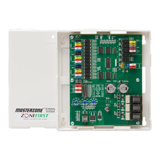
- Page 1 H32P Uni-Zone ™ Model H32P for use with Plug-In Dampers Only Installation and Operating Instructions Controlling Your Comfort Room By Room...
- Page 2 The case. The case has openings in the rear of the case as well as the side for all wiring. Wiring can come from the back as well as the side in order to make a neat installation. ©2017 ZONEFIRST®...
- Page 3 The ZPS and OAS (if used) each require two (2) wires to their SYSTEM – G/E OR HP This switch sets the HVAC Output respective LAS and OAS terminals on the H32P panel. operation. In G/E the Y1 makes as a Cool call and W1 as a ©2017 ZONEFIRST®...
- Page 4 Zone Dampers – The H32P provides DC power to switch can be kept to OFF. ZONEFIRST’s exclusive Plug-In Zone Dampers. These dampers use and are supplied with a modular cord that is Minimum On Timer complete with RJ11 jacks on each end of a 25’...
- Page 5 WIRING DIAGRAM 2 Heat Pump Thermostat ZONE THERMOSTAT C O/B R Y G E WIRING DIAGRAM 6 – Two Speed Compressor Heat Pump W/OB HVAC Equipment – Up to Two WIRING DIAGRAM 3 - Stage Heating and Single Stage Cooling ©2017 ZONEFIRST®...
-
Page 6: Wiring Diagram
To check the zone on the panel, place jumper from R to Y, R to W or R to G to see that the panel is operating properly. Wiring Diagram 6 Aspen Drive – Randolph, NJ 07869-1103 USA Telephone: 1.877.604.1044 Fax: 1.201.794.1359 www.zonefirst.com info@zonefirst.com ©2017 ZONEFIRST®...
Need help?
Do you have a question about the H32P Uni-Zone and is the answer not in the manual?
Questions and answers