Table of Contents
Advertisement
Quick Links
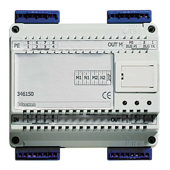
8/2-WIRE interface
Description
8/2-WIRE interface is a device that can be used for installing mixed video door entry
systems, with common backbones using the digital system (8 WIRES), and risers using
the 2 WIRE system.
It is ideal for very large systems as all the performance advantages of the digital system
can be combined with the installation advantages of the 2 WIRE system (simple wiring
system, intercommunication, no need for local power supply of monitors).
The device must be used together with the 346000 power supply.
In installing a system with local entrance panel, the entrance panel itself may be wired
using both the 2 WIRE, or the 8 WIRE procedure.
Related items
346000 (2 WIRE system power supply)
Technical data
Power supply from SCS BUS: 18 – 27 Vdc
Operating temperature:
5 – 40 °C
SELV device
BACKBONE SIDE (IN-OUT):
- Stand-by absorption:
60 mA
- Max. operating absorption: 145 mA
RISER SIDE (EP-OUT M):
- Stand-by absorption:
25 mA
- Max. operating absorption: 110 mA
Dimensional data
6 DIN modules
3
PE
5
6
7
8
PE
1
2
3
4
M1 N1 M2
N2
5
6
7
8
IN
1
2
3
4
IN
Legend
1 - Confi gurator socket
2 - 8 WIRE backbone (IN-OUT) connection clamps
3 - 8 WIRE local entrance panel connection clamp
4 - 2 WIRE riser and power supply connection clamp
5 - Powered device fl ashing (stand by) signalling LED
6 - Local conversation active signalling LED
7 - Conversation with backbone active signalling LED
NOTE: the three fl ashing LEDs indicate a device confi guration error.
346150
4
OUT M
PS
2
1
OUT M
BUS PI
BUS TK
1
6
5
5
6
7
8
OUT
7
1
2
3
4
OUT
2
1
Advertisement
Table of Contents

Subscribe to Our Youtube Channel
Related Manuals for Bticino 346150


Summary of Contents for Bticino 346150
-
Page 1: Technical Data
8/2-WIRE interface 346150 Description 8/2-WIRE interface is a device that can be used for installing mixed video door entry systems, with common backbones using the digital system (8 WIRES), and risers using the 2 WIRE system. It is ideal for very large systems as all the performance advantages of the digital system... - Page 2 346150 Configuration BUS PI BUS TK The device must be physically configured to set the operating mode: M1 N1 M2 N2 MODE A: It is possible to generate up to 40 risers, each with up to 100 handsets (devices). The total number of handsets installed on the riser column must also include any...
- Page 3 346150 Example of confi guration in mode (A) If M1=2 the 100 handsets installed on this riser will take on the absolute address from 201 to 299 and will be confi gured from N=1 to N=99. to other entrance panels...
- Page 4 346150 Example of configuration in mode (B) If M1=12 N1=50 and M2=12 N2=65, on the riser the handsets will have an absolute address going from 1250 to 1265. Therefore the riser handsets must themselves be configured in N from 50 to 65.
-
Page 5: Wiring Diagrams
346150 Wiring diagrams Connection of local 8 WIRE EP Connection of local 2 WIRE EP (PI) (PI) BUS PI BUS PI OUT M OUT M (PE) (PE) BUS 2 1 BUS 2 1 OUT M BUS P I B US TK...
Need help?
Do you have a question about the 346150 and is the answer not in the manual?
Questions and answers