Table of Contents
Advertisement
Advertisement
Table of Contents

Subscribe to Our Youtube Channel
Related Manuals for Danfoss DM430E Series


Summary of Contents for Danfoss DM430E Series
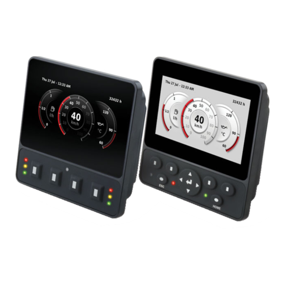
- Page 1 User Manual Engine Information Center (EIC) DM430E Series Display www.danfoss.com...
- Page 2 User Manual DM430E Series Display - Engine Information Center (EIC) Software Revision history Table of revisions Date Changed December 2018 Added note in regards to keeping ambient light sensor area clean and uncovered for best 0102 operation. December 2018 First edition 0101 ©...
-
Page 3: Table Of Contents
User Manual DM430E Series Display - Engine Information Center (EIC) Software Contents User liability and safety statements OEM responsibility................................... 4 Safety statements.....................................4 Display operation guidelines..............................4 Machine wiring guidelines..............................5 Machine welding guidelines..............................5 Overview DM430E Series Display package..............................6 DM430E literature references..............................6 Technical Information (TI)..............................6... -
Page 4: User Liability And Safety Statements
User liability and safety statements OEM responsibility The OEM of a machine or vehicle in which Danfoss products are installed has the full responsibility for all consequences that might occur. Danfoss has no responsibility for any consequences, direct or indirect, caused by failures or malfunctions. -
Page 5: Machine Wiring Guidelines
User Manual DM430E Series Display - Engine Information Center (EIC) Software User liability and safety statements Machine wiring guidelines Warning Unintended movement of the machine or mechanism may cause injury to the technician or bystanders. Improperly protected power input lines against over current conditions may cause damage to the hardware. -
Page 6: Overview
The Engine Information Center (EIC) The DM430E comes installed with the powerful and flexible Danfoss Engine Information Center (EIC) J1939 engine monitor software application. Use the application to customize the look and feel of your individual engine monitoring needs by creating and controlling analog and digital display information in the screen configurations that work best for your performance requirements. -
Page 7: Navigation Using Soft Keys
User Manual DM430E Series Display - Engine Information Center (EIC) Software Overview Up to four signals can be monitored on each screen. Use the EIC software to configure the DM430E for alarms and alerts. Navigation using soft keys The DM430E is controlled by navigation through a set of four soft keys located at the lower front of the display. -
Page 8: Inhibit Regeneration Action
User Manual DM430E Series Display - Engine Information Center (EIC) Software Overview Inhibit Regeneration action If the user selects the Inhibit Regeneration action while the action menu is being displayed the same function as described in Initiate Regeneration action will be executed, with the following. -
Page 9: Main Menu
Use to reset defaults and trip information, access CAN information, select System Setup display settings, and configure PIN settings Basic Setup menu Use Basic Setup to set brightness, color theme, time & date, language, and units for the DM430E Series Display. Basic Setup screen Basic Setup menu... -
Page 10: Brightness
User Manual DM430E Series Display - Engine Information Center (EIC) Software Main Menu Brightness Use the minus (-) and plus (+) soft keys to adjust display screen brightness. After 3 seconds of inactivity the screen will go back to basic setup. -
Page 11: Language
User Manual DM430E Series Display - Engine Information Center (EIC) Software Main Menu Language Use up, down and select soft keys to select program language. Available languages are English, Spanish, French, German, Italian, Swedish and Portuguese. Language screen Units Use up, down, and select soft keys to define units of measurement. -
Page 12: System Info
User Manual DM430E Series Display - Engine Information Center (EIC) Software Main Menu System Info The System Info screen contains hardware serial number, software version, node number and ROP version. System Info screen example Fault Log The Fault Log screen contains saved and stored fault information. Select either Active Faults or Previous Faults to monitor fault activity. -
Page 13: Screen Setup Menu
User Manual DM430E Series Display - Engine Information Center (EIC) Software Main Menu Screen Setup menu Use Screen Setup to select individual screens for setup, and number of signal screens. Screen Setup menu Select screen to set up signal information, screens available are dependent... -
Page 14: System Setup Menu
User Manual DM430E Series Display - Engine Information Center (EIC) Software Main Menu System Setup menu Use System Setup to monitor and control application systems. System Setup menu Use to reset all system information to the default settings Reset Defaults... -
Page 15: Display
User Manual DM430E Series Display - Engine Information Center (EIC) Software Main Menu CAN settings menu Fault Popup Select on/off to enable/disable pop-up messages. Conversion Method Select 1, 2 or 3 to determine how to interpret non- standard fault messages. Consult engine manufacturer for correct setting. -
Page 16: Trip Reset
User Manual DM430E Series Display - Engine Information Center (EIC) Software Main Menu Trip Reset Select Yes to reset all trip data. 16 | © Danfoss | December 2018 AQ288937102741en-000102... -
Page 17: Setup To Monitor Signals
User Manual DM430E Series Display - Engine Information Center (EIC) Software Setup to monitor signals The following steps are for screen setup. Steps 1 through 3 are for selecting number of screens and screen types and 4 through 7 are for selecting J1939 monitor controls. - Page 18 User Manual DM430E Series Display - Engine Information Center (EIC) Software Setup to monitor signals Type 2 is a three-up view with one large signal display capacity and behind it, partially visible, are two small signal display capacities. Screen type 3 Type 3 is a three-up view with one large and two small signal display capacities.
- Page 19 User Manual DM430E Series Display - Engine Information Center (EIC) Software Setup to monitor signals Modify What? screen Modify What? Use to define the signal you would like to display. Signal Use to define gauge icon, range, multiplier and tick settings.
- Page 20 User Manual DM430E Series Display - Engine Information Center (EIC) Software Setup to monitor signals 7. After making a signal selection, press the right arrow soft key to go to the next selection area. • Use left arrow, right arrow, and next soft keys to select signal monitoring screen.
-
Page 21: Symbols For J1939 Parameters
User Manual DM430E Series Display - Engine Information Center (EIC) Software Setup to monitor signals Symbols for J1939 parameters The following table lists symbols for the J1939 engine and transmission parameters that are available and can be monitored. Symbols for the J1939 engine and transmission parameters... - Page 22 User Manual DM430E Series Display - Engine Information Center (EIC) Software Setup to monitor signals Symbols for the J1939 engine and transmission parameters (continued) Symbol Name/Function Symbol Name/Function Heat exchanger, coolant fluid radiator; radiator Fuel system failure; malfunction Fuel pressure...
- Page 23 User Manual DM430E Series Display - Engine Information Center (EIC) Software Setup to monitor signals Symbols for the J1939 engine and transmission parameters (continued) Symbol Name/Function Symbol Name/Function Engine, electrical preheat (low temperature start aid) Separator-drive oil Separator-drive oil pressure...
- Page 24 User Manual DM430E Series Display - Engine Information Center (EIC) Software Setup to monitor signals Symbols for the J1939 engine and transmission parameters (continued) Symbol Name/Function Symbol Name/Function Engine emissions system temperature; diesel Diesel exhaust fluid (DEF); selective catalyst reduction...
-
Page 25: Led Indicators
User Manual DM430E Series Display - Engine Information Center (EIC) Software LED indicators Particulate filter lamp Stage 1 The right Amber LED indicates the initial need for regeneration. The lamp is on solid. Stage 2 The right Amber LED indicates an urgent regeneration. -
Page 26: Installation And Mounting
User Manual DM430E Series Display - Engine Information Center (EIC) Software Installation and mounting Mounting Recommended mounting procedure mm [in] 115.40 [4.54] 104.50 [4.11] 107.50 [4.23] 99.50 [3.92] 4 x R3 Callout Description Panel opening for mounting on surface A... -
Page 27: Fastening
User Manual DM430E Series Display - Engine Information Center (EIC) Software Installation and mounting Fastening Caution • Use of non-recommended screws can cause damage to housing. • Excessive screw torque force can cause damage to housing. Maximum torque: 0.9 N m (8 in-lbs). - Page 28 User Manual DM430E Series Display - Engine Information Center (EIC) Software Installation and mounting DEUTSCH DTM06-12SA 12 pin (continued) C1 pin DM430E-0-x-x-x DM430E-1-x-x-x DM430E-2-x-x-x DigIn/AnIn DigIn/AnIn DigIn/AnIn DigIn/AnIn CAN 1+ Sensor power DigIn/AnIn CAN 1- Secondary power input Multifunction input (DigIn/AnIn/Freq/4-20...
-
Page 29: Ordering Information
User Manual DM430E Series Display - Engine Information Center (EIC) Software Ordering information Model variants Part number Order code Description 11197958 DM430E-0-0-0-0 4 Buttons, I/O 11197973 DM430E-1-0-0-0 4 Buttons, 2-CAN 11197977 DM430E-2-0-0-0 4 Buttons, Sensor Power, Secondary Power Input 11197960... -
Page 30: Related Products
User Manual DM430E Series Display - Engine Information Center (EIC) Software Ordering information D—Button Pads Description 4 Buttons, 6 LEDs Navigation buttons, 2 Dual-color LEDs E—Application key Description (EIC Application) No Application Key Application Key (EIC Application) Related products Connector bag assembly... - Page 31 User Manual DM430E Series Display - Engine Information Center (EIC) Software © Danfoss | December 2018 AQ288937102741en-000102 | 31...
- Page 32 User Manual DM430E Series Display - Engine Information Center (EIC) Software 32 | © Danfoss | December 2018 AQ288937102741en-000102...
- Page 33 User Manual DM430E Series Display - Engine Information Center (EIC) Software © Danfoss | December 2018 AQ288937102741en-000102 | 33...
- Page 34 Phone: +86 21 3418 5200 Danfoss can accept no responsibility for possible errors in catalogues, brochures and other printed material. Danfoss reserves the right to alter its products without notice. This also applies to products already on order provided that such alterations can be made without subsequent changes being necessary in specifications already agreed.
Need help?
Do you have a question about the DM430E Series and is the answer not in the manual?
Questions and answers