DriSteem ULTRA-SORB XV Installation, Operation And Maintenance Manual
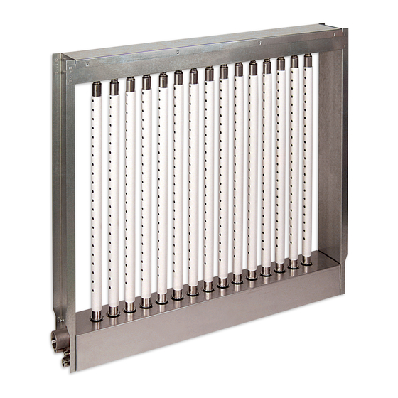
Steam dispersion panel.
for pressurized steam applications
Hide thumbs
Also See for ULTRA-SORB XV:
- Installation, operation and maintenance manual (20 pages) ,
- Installation, operation and maintenance manual (40 pages)

Subscribe to Our Youtube Channel
Related Manuals for DriSteem ULTRA-SORB XV


Summary of Contents for DriSteem ULTRA-SORB XV
- Page 1 READ AND SAVE THESE INSTRUCTIONS ULTRA-SORB ® MODEL S team Dis p er si on P anel Installation, Operation, and Maintenance Manual For pressurized steam applications...
-
Page 2: Table Of Contents
Mounting in an air handler ......11 Recommendations and steam inlets ......12 DriSteem technical support Controls 800-328-4447 Float switch . - Page 3 K Pressurized condensate 19.5 3/4" NPT (DN20) outlet (internal thread) * If face height is <17" (432 mm), consult DriSteem or see DriCalc for • 1" (DN25) connection, same as the correct calculation. dimension A; • 2" (DN50) connection, dimension A L Overall width + 1"...
-
Page 4: Installation
INSTALLATION Field assembly UNPACK THE DISPERSION ASSEMBLY AND LOOSE COMPONENTS • Ultra-sorb Model XV has High-Effi ciency Tubes. These dispersion tubes are insulated with polyvinylidene fl uoride (PVDF) insulation, which provides up to an 85% reduction in wasted energy by signifi cantly reducing airstream heat gain and condensate production. - Page 5 INSTALLATION Field assembly LAY OUT THE PANEL COMPONENTS Note: These assembly instructions are for Ultra-sorb Model XV panels shipped Orient the panel components on a large, fl at working surface. unassembled by request or as required. Panels with overall height more ATTACH THE FLANGES than 98"...
-
Page 6: Piping
INSTALLATION Piping FIGURE 4-1: ULTRA-SORB MODEL XV PIPING COMPONENTS (WITH FLOAT SWITCH), FIGURE 4-2: ULTRA-SORB STRAINER PRESSURIZED STEAM SOURCE Install inlet strainer (same size as valve, or larger than valve) within Standard trap piping Ultra-sorb Model XV 3' (1 m) of Ultra-sorb steam dispersion panel Valve Electric modulating steam valve... - Page 7 INSTALLATION Piping FIGURE 5-1: ULTRA-SORB MODEL XV PIPING WITH STS HUMIDIFIER Steam to heat exchanger from pressurized steam source, humidifi cation steam from STS humidifi er Dispersion tube Insulated copper Connection end of header steam supply tubing (see inset below) Header DM-11136b Cold fi...
-
Page 8: Selecting The Location
INSTALLATION Selecting the location FIGURE 6-1: PLACING A DISPERSION ASSEMBLY IN AN AIR HANDLING UNIT Filters Cooling coil 8' to 12' (2.4 to 3.7 m) Heating coil Economizer Duct high limit humidity control control device for dispersion locations A, B Airfl... - Page 9 INSTALLATION Selecting the location DETERMINE HUMIDIFIER PLACEMENT Dispersed steam must be absorbed into the airfl ow before it comes in contact with duct elbows, fans, vanes, fi lters, or any object that can cause condensation and dripping. • Install the Ultra-sorb panel in a location where discharged water vapor will be absorbed by the airstream.
-
Page 10: Mounting And Support
INSTALLATION Mounting and support INSTALLATION IN A COLD AIR STREAM FIGURE 8-1: INSTALLATION IN A COLD AIR STREAM When a humidifi er is installed in a duct that will carry cold air, determine the dew point temperature. If the psychrometric chart reveals that saturation may Extended trails of fog may develop occur, protection should be provided. -
Page 11: Mounting In A Duct
INSTALLATION Mounting and support Ultra-sorb Model XV heat exchanger must use steam from pressurized steam Duct smoke detector source only. Humidifi cation steam can be from pressurized steam source or STS Do not install a duct smoke detector downstream from the Ultra-sorb panel. If steam-to-steam humidifi... -
Page 12: Installation Drawings Mounting In A Duct
INSTALLATION Installation drawings: Mounting in a duct FIGURE 10-1: ULTRA-SORB MODEL XV IN A DUCT (HORIZONTAL AIRFLOW ONLY) Attach duct fl ange to top frame assembly No screws 1/2" (13 mm) Screws OK Attach duct fl anges to 1.5" (38 mm) mounting fl anges No screws through top of header assembly Attach duct fl... -
Page 13: Mounting In An Air Handler
• Recommended fasteners for mounting the Ultra-sorb to a metal support frame are 1/4–20 nuts and bolts or #12 self drilling and tapping screws. • Due to possible forces exerted on this application, DriSteem recommends fastener spacing not to exceed 6" (150 mm). -
Page 14: Recommendations And Steam Inlets
INSTALLATION Recommendations and steam inlets RECOMMENDATIONS Integral heat exchanger Trapping • Ultra-sorb Model XV employs an integral heat exchanger to pressurize and lift • Low pressure, up to 15 psi (103 kPa) — fl oat and thermostatic (F&T) condensate up to 12" per psi (300 mm trap (Figures 12-1 and 12-2) per 6.9 kPa) of steam pressure. -
Page 15: Controls
Install the temperature switch (Figure 19-1) to prevent the header from fl ooding with condensate if the heat exchanger cools, such as if the condensate return main becomes fl ooded or the trap fails closed. DriSteem's temperature switch is a temperature-actuated make-break switch. The temperature at which it switches is adjustable and should be set at 210 °F (99 °C). -
Page 16: Heat Exchanger Time Delay
INSTALLATION Controls HEAT EXCHANGER TIME DELAY Systems that stop humidifying for extended periods of time may have two reasons for a time delay: To conserve energy, and to dry the header and remove standing water that might allow for microbe growth. To dry the header, pressurized steam can be set to fl... -
Page 17: Control Cabinet
INSTALLATION Controls FIGURE 15-1: ULTRA-SORB MODEL XV CONTROL CABINET 12" (305 mm) OM-7533 mc_101410_0820 12" (305 mm) 6" (152 mm) Notes: • Electrical power requirements: 120 VAC, 0.2 Amps, or 240 VAC, 0.1 Amps • Components are 24 VAC, powered by a transformer in the control cabinet. -
Page 18: Wiring Diagrams
INSTALLATION Wiring diagrams FIGURE 16-1: ULTRA-SORB MODEL XV CONTROL CABINET FIELD WIRING, ELECTRIC MODULATING STEAM VALVE External connections XV-1 ULTRA-SORB MODEL XV INSTALLATION, OPERATION, AND MAINTENANCE MANUAL... - Page 19 INSTALLATION Wiring diagrams FIGURE 17-1: ULTRA-SORB MODEL XV CONTROL CABINET FIELD WIRING, PNEUMATIC MODULATING STEAM VALVE Pneumatic supply by others, 0-20 psi (0-138 kPa) External connections DISP-3-C mc_052010_0600 ULTRA-SORB MODEL XV INSTALLATION, OPERATION, AND MAINTENANCE MANUAL...
-
Page 20: Operation
OPERATION Sequence of operation 1. HEAT EXCHANGER ON-OFF SOLENOID VALVE FIGURE 18-1: ULTRA-SORB MODEL XV See Figure 18-2. WITH STS; STEAM INLETS DETAILED Humidifi cation Upon a call for humidity, the heat exchanger on-off solenoid valve opens, steam from STS and pressurized steam fl... - Page 21 OPERATION Sequence of operation 5. HEAT EXCHANGER FIGURE 19-1: Pressurized steam enters the heat exchanger inlet (5a). The heat exchanger TEMPERATURE SWITCH SENSOR vaporizes dispersion-generated condensate, while pressurized condensate (5b) returns to the boiler via the condensate return main. Temperature switch sensor (install 6.
-
Page 22: Start-Up
OPERATION Start-up 1. Prime the header overflow P-trap, if installed. Ensure that it is installed as CAUTION recommended in “Optional header overflow P-trap water seal” on Page Remove clear poly fi lm; do not remove white PVDF insulation. 2. Turn on steam to the heat exchanger. Inspect connections for piping leaks. High-Effi... -
Page 23: Performance Data
• Ultra-sorb panels with 9" (225 mm) or 12" (300 mm) tube spacings have no measurable air pressure loss. • Use DriSteem’s DriCalc sizing and selection software to calculate your specifi c air pressure loss. mc_101410_0846 ULTRA-SORB MODEL XV INSTALLATION, OPERATION, AND MAINTENANCE MANUAL... -
Page 24: Maintenance
MAINTENANCE Strainer, traps, and valves STRAINER Inspect at least twice during the fi rst year. If fouled, inspect it more frequently. STEAM TRAPS At least twice a year verify that the steam traps are functioning properly. A blocked steam trap is room temperature. A “blowing” steam trap is hot and noisy, and the discharge pipe from it is hot for 30 feet (9 m). -
Page 25: Dispersion Tubes And Heat Exchanger
• If steam or condensate is evident at the sealing surface, replace the seal. • Inspect insulating material for tears; repair with Insulating Material Repair Kit (available from your local DriSteem representative) before dispersing steam or moving air through the air handler to prevent further damage. -
Page 26: Humidifier De-Scaling Solution
MAINTENANCE Humidifi er De-scaling Solution Material deposits can be removed from the heat exchanger with DriSteem’s See DriSteem’s Humidifi er De-scaling Solution on the Accessories and options page (under Humidifi er De-scaling Solution, available for purchase from your DriSteem Products) on our website: www.dristeem.com representative or distributor. -
Page 27: Replacement Parts
MAINTENANCE Replacement parts FIGURE 25-1: ULTRA-SORB MODEL XV REPLACEMENT PARTS OM-7484b mc_101410_0835 Table 25-1: Table 25-2: Ultra-sorb Model XV replacement parts Ultra-sorb Model XV replacement components No. Description Part No. Description Part No. 1 Screws, frame (package of 4) 191170-010 Electric modulating steam valve consult factory 2 O-ring, square 1.35"... -
Page 28: Troubleshooting
• Ensure humidifi cation is 43 lbs/hr (19.5 kg/h) per tube or less.. tube Note: For panels with a face height less than 17" (430 mm), contact DriSteem for assistance. • Steam main overloaded with water due to boiler • Locate cause of priming and correct. - Page 29 MAINTENANCE Troubleshooting Table 26-1: Ultra-sorb Model XV troubleshooting guide (continued) Problem Possible cause Action Control system • Incorrect control voltage • Replace transformer. malfunctioning • Incorrect control signal • Replace components. • Improper wiring connections • Rewire. • Incorrect humidity sensor •...
- Page 30 • Compressed air pressure is too low • Adjust pressure. rise to humidistat set point • Temperature control switch not allowing • Consult DriSteem to assess whether installed panel is correct for (continued) modulating steam valve to operate application. • Foreign matter preventing valve from closing • Clean or replace valve.
- Page 31 ULTRA-SORB MODEL XV INSTALLATION, OPERATION, AND MAINTENANCE MANUAL...
-
Page 32: Warranty
DriSteem, or if the products have been For the most recent product information modifi ed or altered without the written consent of DriSteem, or if such products have been subject visit our Web site: www.dristeem.com to accident, misuse, mishandling, tampering, negligence or improper maintenance.
Need help?
Do you have a question about the ULTRA-SORB XV and is the answer not in the manual?
Questions and answers