Sigfox SMBS-T4 Product Manual
Micro access station
Hide thumbs
Also See for SMBS-T4:
- Quick start manual (2 pages) ,
- Quick start manual (6 pages) ,
- Product manual (17 pages)
Table of Contents
Advertisement
SMBS-T4-PROD-MAN v1
Sigfox Access
Station Micro
SMBS-T4
Product manual
November 2018
N
ote: Only the last version of this document available on the Sigfox technical system documentation is official and
applicable. This document is confidential and is the property of Sigfox. It shall not be copied and / or disclosed to third
parties, in any form without Sigfox written permission.
Advertisement
Table of Contents

Related Manuals for Sigfox SMBS-T4


Summary of Contents for Sigfox SMBS-T4
- Page 1 Only the last version of this document available on the Sigfox technical system documentation is official and applicable. This document is confidential and is the property of Sigfox. It shall not be copied and / or disclosed to third...
-
Page 2: Table Of Contents
Table of content Product presentation ........................3 Network overview ......................... 3 Package contents ......................... 4 Installation site recommendation ....................4 4.1. Equipment ..........................4 4.2. Coexistence with another RF equipment ................4 4.3. Site selection ......................... 5 4.4. Outdoor protection ......................... 7 Connection and commissioning .................... -
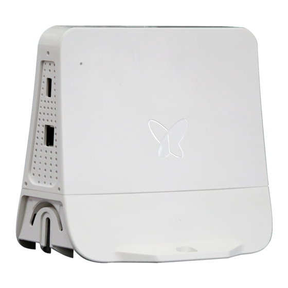
Page 3: Product Presentation
1. Product presentation Sigfox Access Stations operate on a specific frequency bandwidth used by sigfox devices. They perform mainly receiving operations (uplink), but are also able to transmit information by doing downlink operations upon device request The Access Stations Micro include a complete system described in the network overview below. -
Page 4: Package Contents
3. Package contents Sigfox Access Station Micro SBMS-T4 Mounting kits (2 ties and 2 set of screws and anchors) PoE DC injector Ethernet cable CAT6 1.5m Power adaptor 110/220V AC to 24V DC 18W Quick Start Guide / Safety Notice Accessories available separately: ... -
Page 5: Site Selection
The station should not be used within a metallic closet or in a technical room with metallic door. Avoid placing the Sigfox devices in the same room as the station. Should all the devices be at close proximity, check with the local Operator how to... - Page 6 Avoid installation on the last floor in case of cellular BS on the roof and away from windows to reduce RF interferers from cellular/broadcasters” When installed vertically on a wall, the connector must be facing downward. Outdoor: It is recommended for pole and wall installation to place the Access Station Micro above, in the periphery of and facing the connected devices for best result.
-
Page 7: Outdoor Protection
Central position 4.4. Outdoor protection To install the Access station micro outside, or in an environment exposed to high humidity, dust, or even to prevent thief, you must use the sealing cover to protect the connectors and the USB dongle if used. The sealing cover provides an Ingress Protection IP65. -
Page 8: Connection And Commissioning
5. Connection and commissioning 5.1. Interface port Ethernet port 5.2. Power supply The station is powered with a PoE. The PoE splitter is integrated in the station. The power is conveyed from the AC/DC adapter through the DC injector and the ETH cable. -
Page 9: Power Consumption
Backup connectivity can be provided with a compatible 3G or 4G USB dongle (see §3 Package contents). Configuration of the cellular connectivity is not yet available via the Sigfox portal and must be done with Access Station tool (see next §5.4 Commissioning). -
Page 10: Commissioning
For more details, please contact your Sigfox Operator. 5.4. Commissioning Commissioning of the station is done online by the Sigfox Operator via the Backend interface. Pre-commissioning can also be done with Access Station utility by connecting a suitable phone or tablet to the USB port of the station. -
Page 11: Led Status
5.5. LED status Meaning Troubleshooting Check power supply, injector and Ethernet No power cable (for ≈30 secs) Power on If the light remains red after 2 minutes, try to unplug and plug again the station. If the – Solid (> 1 Hardware issue problem persists, contact your support. -
Page 12: Annexes
6. Annexes 6.1. Labels 6.1.1. Product ID Model : SMBS-T4 Input : 12V / 5.4A S/N : 00003421 OF number : sigfox 425 rue Jean Rostand 31670 Labège, France www.sigfox.com Designed in France Assembled in Spain 6.1.2. Compliances Certifications for other countries or regions are still ongoing. New certifications will be added over time, without product modification. -
Page 13: Specifications
6.2. Specifications RADIO CHARACTERISTICS Standard Sigfox Ultra Narrow Band Protocol for M2M and IoT Max range of operating 865 to 928 MHz frequencies * Receiver Sensitivity -132dBm @ 100bps / -124dBm @ 600bps Data Rate and Modulation 100 bps D-BPSK (UL) 600 bps GFSK (DL) Max Transmit Power * (EIRP) 23 dBm ±... - Page 14 MECHANICAL AND ENVIRONMENTAL Product weight 450g (1 lb) Operating temperatures -20°C to +55°C Storage temperatures -30°C to +85°C Robustness MTBF 92,000 hours Casing material Plastic ASA/PC Dimensions (in mm): Sealing cover:...
Need help?
Do you have a question about the SMBS-T4 and is the answer not in the manual?
Questions and answers