Table of Contents
Advertisement
PNEUMERCATOR
Liquid Level Control Systems
AUDIBLE ALARM CONTROLS
Peter Sinkiwskij
Digitally signed by Peter Sinkiwskij
DN: cn=Peter Sinkiwskij, o=Pneumercator Co., Inc., ou=Headquarters, email=peter@pneumercator.com, c=US
Date: 2017.08.03 12:45:24 -04'00'
INSTRUCTION MANUAL
Revised: July 2, 2017
DRAWING NO. 20000 REV. A
LC1000 SERIES
INTRINSICALLY SAFE
ALARM CONSOLE
© COPYRIGHT 2017 PNEUMERCATOR CO., INC.
1785 EXPRESSWAY DRIVE NORTH
HAUPPAUGE, NY 11788
(631) 293-8450 Phone
(631) 293-8533 Fax
(800) 209-7858 Support
www.pneumercator.com
LC100x Instruction Manual - 2017-07-02.docx
Advertisement
Table of Contents

Subscribe to Our Youtube Channel
Related Manuals for Pneumercator LC1000 SERIES


Summary of Contents for Pneumercator LC1000 SERIES
- Page 1 PNEUMERCATOR Liquid Level Control Systems AUDIBLE ALARM CONTROLS Peter Sinkiwskij Digitally signed by Peter Sinkiwskij DN: cn=Peter Sinkiwskij, o=Pneumercator Co., Inc., ou=Headquarters, email=peter@pneumercator.com, c=US Date: 2017.08.03 12:45:24 -04'00' INSTRUCTION MANUAL Revised: July 2, 2017 DRAWING NO. 20000 REV. A LC1000 SERIES...
-
Page 3: Table Of Contents
LC1000 INSTRUCTION MANUAL TABLE OF CONTENTS TABLE OF CONTENTS Page SAFETY INFORMATION ..................5 Section 1 PRODUCT DESCRIPTION ..................x 1.1 General System Overview ..................6 1.2 Control Console Description ................... 7 1.3 Liquid Sensor Description ..................10 Section 2 INSTALLATION DETAILS .................. -
Page 5: Safety Information
The following warnings must be considered to be in compliance with accepted codes. Any inquiries about this manual, or to return defective equipment should be directed to: PNEUMERCATOR COMPANY 1785 EXPRESSWAY DRIVE NORTH HAUPPAUGE, NY 11788 Attention: Technical Services TEL: (631) 293-8450... -
Page 6: Product Description
RELAY OUTPU T PIPING SUM P LEAK SENSO R LIQUID FILLED RESERVOIR LEAK SENSO R HIGH LEVEL SWI TCH 90% CAPACITY TYPICA L TYPICAL FIBERGLASS DOUBLE WALL TAN K DRAWING NO. 20058 REV. A Figure 1-1 - LC1000 Series Overview PAGE 6... -
Page 7: Control Console Description
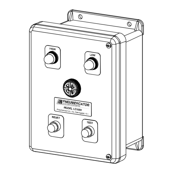
LC1000 INSTRUCTION MANUAL PRODUCT DESCRIPTION 1.2 CONTROL CONSOLE DESCRIPTION The console is housed in a NEMA 4X (weather tight/corrosion resistant) FRP (fiberglass reinforced plastic) enclosure for mounting in the non-hazardous area. Each unit operates on 120 VAC power and provides from one (1) to four (4) intrinsically safe alarm channels for monitoring up to four independent sensing points. - Page 8 8 3 4 9 1 2 [222] [242] PNEUMERCATOR PNEUMERCATOR Liquid Level Control Systems Liquid Level Control Systems MODEL LC1000 MODEL LC1000 Pneumercator Co., Inc. Farmingdale, N.Y. Pneumercator Co., Inc. Farmingdale, N.Y. RESET TEST RESET TEST RESET TEST OPTIONAL 316 STAINLESS PUSHBUTTON...
- Page 9 LC1000 INSTRUCTION MANUAL PRODUCT DESCRIPTION WARNING Do not drill or modify enclosure. Use only conduit entries provided. FAILURE TO COMPLY WILL VOID WARRANTY AND MAY PRESENT A SAFETY HAZARD RESULTING IN PERSONAL INJURY, PROPERTY LOSS AND EQUIPMENT DAMAGE. WARNING Conduit entries must only be used for their designated purpose in order to assure safe operation and to maintain safety certification.
-
Page 10: Liquid Sensor Description
Figures 1-5 through 1-8 show four (4) sensor types provided by Pneumercator with their most typical applications. Other non-Pneumercator models may be used; however, their use with the LC1000 should have been approved by Pneumercator and local regulators before attempting to wire them into the system. - Page 11 LC1000 INSTRUCTION MANUAL PRODUCT DESCRIPTION LS600, LS600 OW OR LS600A * LS600A NCL 5" REF. 1/2" NPT THREADED OPENING (2) 10' LONG 18 AWG (2) 2' LONG (10' FOR LS600A MODELS) HOUSING WIRE LEADS 18 AWG WIRE LEADS PER FLOAT SWITCH 5 1/2"...
- Page 12 LC1000 INSTRUCTION MANUAL PRODUCT DESCRIPTION 16' LONG 22 AWG CABLE CABLE GRIP PVC HOUSING FLOAT HIGH ALARM 18.25" 11.00" 15.00" ALARM 2.25" Ø2.88" DRAWING NO. 20056 REV. N/C Figure 1-8 – RSU800 (Refer to Bulletin 134 for Installation/Operation/Testing Instructions) Commonly used in Wet Interstitial Spaces of Fiberglass Tanks PAGE 12...
-
Page 13: Installation Checklist
LC1000 INSTRUCTION MANUAL INSTALLATION DETAILS SECTION 2 – INSTALLATION DETAILS 2.1 INSTALLATION CHECKLIST WARNING Do NOT apply power to the LC1000 until its installation has been checked and found to be in accordance with these instructions; National Electric Code; Federal, State and Local codes; and other applicable safety codes. FAILURE TO COMPLY MAY RESULT IN PERSONAL INJURY, PROPERTY LOSS AND EQUIPMENT DAMAGE. -
Page 14: Installation Details
LC1000 INSTRUCTION MANUAL INSTALLATION DETAILS 2.2 CONTROL CONSOLE INSTALLATION The console is the center of operations for any tank monitor system therefore its location should be selected for the operator’s convenience, or as specified on the DESIGN DRAWINGS. Select a flat wall surface and prepare it with four wall-mounting inserts to accept up to 1/4-inch size bolts. - Page 15 LC1000 INSTRUCTION MANUAL INSTALLATION DETAILS CHAMFERED CORNER BOARD #1 (LEFT): I.S. COMPARTMENT COVER W/ CHAMFERED CORNE R (SHOWN OUTSIDE CONSOLE ) BOARD #2 (RIGHT): I.S. COMPARTMENT COVE R (SHOWN OUTSIDE CONSOLE ) I.S. GROUNDS BOARD #1 (LEFT ): I.S. INPUTS 1 & 2 FOR LC1003 AND LC100 4 BOARD #2 (RIGHT): I.S.
-
Page 16: Leak Sensor Installation - Steel Tanks
The cap or reducer bushing IS NOT SUPPLIED with the sensor and must be provided by the installer. A 2” (SK2) or 4” (SK4) Sensor Cap Kit can be ordered separately from Pneumercator). 3. Measure the "MOUNTING HEIGHT" from top to bottom of monitoring pipe. -
Page 17: Leak Sensor Installation - Piping Sumps And Dispenser Pans, Vaulted Tank
LC1000 INSTRUCTION MANUAL INSTALLATION DETAILS 2.4 LEAK SENSOR INSTALLATION IN PIPING SUMPS AND DISPENSER PANS Check the specific design drawings for the job, or use the LS600LD Series as illustrated in Figure 1-5. Install sensor per Figure 2-3 as follows: 1. -
Page 18: Leak Sensor Installation - Fiberglass Underground Tanks
2” (SK2) or 4” (SK4) Sensor Cap Kit can be ordered 12 Feet 222 in. separately from Pneumercator). 4. At riser top, attach the annular space PULL CORD (this is part of the tank supplier's pre-installed accessories) to the sensor's PULL HOLE. -
Page 19: Other Dry Contact Float Switches
LC1000 has not been specifically approved for use with sensors not manufactured by Pneumercator. Please consult with your local regulators and with Pneumercator to discuss the compatibility of your particular sensor with the console and application. -
Page 20: Wiring Installation And Diagrams
SECTION 3 WIRING INSTALLATION AND DIAGRAMS 3.1 PC BOARD LAYOUT AND SETUP The LC1000 Series includes either one (LC1001/LC1002) or two (LC1003/LC1004) PC boards within the enclosure. These PC Boards will be setup at the factory to match the sensors provided on the order. - Page 21 LC1000 INSTRUCTION MANUAL WIRING ITEM FUNCTION Sensor Terminal Block Power and Relay Contact Terminal Block Intrinsically Safe Earth Ground Terminal Power Fuse: 0.1 Amp, Slo-Blow JP3- JP6 Relay Control Jumper Plug Schedule/Each PC Board (Jumper Field Sensor Jumper Position Dry Contacts Output at Plugs) Normal Condition on PC Board...
- Page 22 LC1000 INSTRUCTION MANUAL WIRING Sensor Model Normal Contact State LS600LD Series OPEN (see note 1) LS600 (Striped wire pair) OPEN (dry state, see note 2) LS600 (Solid Color wire pair) CLOSED (dry state, see note 2) LS600-S OPEN LS610 CLOSED RSU800 CLOSED Note 1: The LS600LD Series is shipped from the factory as normally open unless otherwise noted.
-
Page 23: System Wiring
LC1000 INSTRUCTION MANUAL WIRING CAUTION Sensors connected to the LC1000 are usually installed in explosion hazard areas typical of hydrocarbon fuel tanks. For these applications, it is CRITICAL that electrical conduit and wiring be installed by qualified installers familiar with all provisions of the National Electrical Code relating to equipment intended for use in EXPLOSION HAZARD areas. - Page 24 (GROUND BUSS BAR) IN THE SAME SERVICE PANEL AS LC POWER. A GROUNDING ROD, COLDWATER PIPE OR OTHER CONNECTION SHOULD NOT BE USED. 4. INTRINSIC SAFETY COVER/BARRIER MUST REMAIN IN PLACE. PNEUMERCATOR Liquid Level Control Systems 50100 Rev. D (07/25/05)
- Page 25 (GROUND BUSS BAR) IN THE SAME SERVICE PANEL AS LC POWER. A GROUNDING ROD, COLDWATER PIPE OR OTHER CONNECTION SHOULD NOT BE USED. 4. INTRINSIC SAFETY COVER/BARRIER MUST REMAIN IN PLACE. PNEUMERCATOR Liquid Level Control Systems 50101 Rev. D (07/25/05)
- Page 26 LC1000 INSTRUCTION MANUAL WIRING 5. The alarm console is separated into two wiring sections, for each printed circuit board, by an aluminum cover. The wiring and terminal block on the left side are intrinsically safe and are physically separated from the AC power wiring on the right side. This separation must be maintained.
-
Page 27: Sensor Map/System Setup
A single pair of wires per signal would connect the main system via the dry contact output to the LC1000 on the Switch input. All Pneumercator systems equipped with relay outputs are considered dry contact, or outputs without power. Other equipment manufacturers may use powered relay outputs. Consult the system manufacturer to determine if the system is equipped with outputs that are dry contact that can be used to represent the desired alarm condition. -
Page 28: Operation
LC1000 INSTRUCTION MANUAL OPERATION SECTION 4 OPERATION 4.1 GENERAL The LC1000 Alarm system provides three (3) functions when a field sensor experiences an alarm condition: A light comes on, a horn annunciates and a relay changes state. The horn may be silenced by pressing the RESET button, but the light will stay on and the relay will remain in the alarm state as long as the field sensor remains in the alarm condition, e.g., high liquid level. -
Page 29: Troubleshooting
LC1000 INSTRUCTION MANUAL TROUBLESHOOTING SECTION 5 TROUBLESHOOTING 5.1 GENERAL The On/Off switching control operation of the LC1000 makes it simple to test and troubleshoot the system. Pressing the TEST button performs a functional test of the horn, all indicator lights and all relay contacts. -
Page 30: Maintenance/Testing
LC1000 INSTRUCTION MANUAL MAINTENANCE SECTION 6 MAINTENANCE/TESTING 6.1 CONSOLE The operation of the LC1000 lights, horn, and relays can be verified by holding down the TEST button. The TEST button causes all alarm conditions for the system to go to the alarm state. For this reason, it is best to do this with at least one alarm condition in the normal state otherwise your horn will not activate since there are no new alarm conditions detected. - Page 32 This constitutes our obligation and none other stated for any purpose except the above shall apply. Contact Pneumercator for detailed warranty documentation. REVISION 101008 Distributed by: PNEUMERCATOR Liquid Level Control Systems Pneumercator Co.
Need help?
Do you have a question about the LC1000 SERIES and is the answer not in the manual?
Questions and answers