Table of Contents
Advertisement
Advertisement
Table of Contents

Related Manuals for ECGMAC EM-301


Summary of Contents for ECGMAC EM-301
- Page 2 ECGMAC assumes no consequence caused by the publication. Any part of the manual shall not be reproduced, photocopied in any form without prior written permission from ECGMAC.ECGMAC reserve the right to change, update, revise the product...
-
Page 4: Table Of Contents
Contents 1 Safety Guidance......................3 1.1 Installation and storage ..........................3 1.2 Before operation ............................3 1.3 During operation............................3 1.4 After operation............................. 4 1.5 EMC and relevant notes..........................4 1.6 Device classification............................ 4 1.7 Measurement requirement ........................... 5 1.8 Discarding the equipment ..........................5 1.9 Symbols ............................... - Page 5 5.3 Operation mode ............................29 5.4 Leads setup ..............................36 5.5 Display setup ............................. 37 5.6 System setting............................38 6 Cleaning, Disinfection and Maintenance ..............46 6.1 Cleaning..............................46 6.2 Disinfection ............................... 46 6.3 Care and Maintenance ..........................47 7 Common troubleshooting and solution ..............49 7.1 Some lead without waveform printout.......................
-
Page 6: Safety Guidance
1 Safety Guidance This is provided for the use of qualified physicians or personnel professionally trained. The operator is supposed to be familiar with the contents of this Operation Manual before operation. This is applicable for ECG signal acquisition, recording and analysis. 1.1 Installation and storage Avoid contact with water. -
Page 7: After Operation
1.4 After operation Reset all the function setup to the initial state and shut down the power; Gently remove the electrodes, and do not harshly drag the wires; Clean the instrument and accessories for the later use. 1.5 EMC and relevant notes This instrument complies with IEC60601-1-2 standard about the medical electronic equipment safety standards on electromagnetic compatibility. -
Page 8: Measurement Requirement
Combustible gas safety: Not suitable for use under the presence of flammable gas Mode of operation: Continuous EMC: Class B 1.7 Measurement requirement ECG belongs to measurement instrument. The users are suggested to send the instrument to authorized Measurement Institutes for verification at least once a year according to the state ECG and EEG metrological verification regulations. -
Page 9: Recording Paper
To guarantee the record quality of the ECG waveforms, please use the high speed thermal paper supplied or appointed by ECGMAC. Other paper may shorten print head’s life. And the deteriorated print head may lead to illegible ECG record and block the advance of paper etc Please do pay attention to the following aspects:... -
Page 10: Safety Information
Only qualified service engineers can install this equipment. And only service engineers authorized by ECGMAC can open the shell case. Auxiliary equipments connected to the digital and analog interfaces must be certified according to IEC standards (e.g. IEC950 for data processing equipment and IEC60601-1 for medical equipment). -
Page 11: Warnings For Rechargeable Lithium Battery
The operator should not touch patient, patient bed, table or instrument when it use simultaneous with the defibrillator or pacemaker. Please use the patient cable and other accessories supplied by ECGMAC. Otherwise, it will affect the performance and function, even damage the ECG. -
Page 12: General Notes
Do not use the battery near fire or place over 60℃. Don’t heat or splash the battery. Do not throw the battery into fire or water. Do not ruin the battery by hammering, beating, chiseling a metal into it or other else, which will cause the battery to be deformation, heat, to smoke, burn and other danger. - Page 13 Be sure that there is no intense electromagnetic interference source around the equipment, such as radio transmitter or mobile phone etc. Attention: large medical electrical equipment such as electrosurgical equipment, radiological equipment and magnetic resonance imaging equipment etc. are likely to bring electromagnetic interference. Check the main unit and its accessories carefully before operating the ECG for patients.
-
Page 14: Cleaning, Disinfection, Maintenance
The instrument signal input/output connector (when needed) must be connected with Class I equipment which is GB9706.1-compliant, and the total leakage current should be tested to be available by users themselves. Electrical schematic diagram and parts lists are only available to qualified repair stations or staff of ECGMAC authorized. -
Page 15: Intended Use
2.5 Intended Use The intended use is to acquire ECG signals from human through body surface ECG electrodes. The ECG recorded by the electrocardiograph can help users to analyze and diagnose heart disease. 2.6 Contraindication Absolute Contraindication 1. Acute myocardial infarction (within 2days) 2. -
Page 16: Structure And Principle
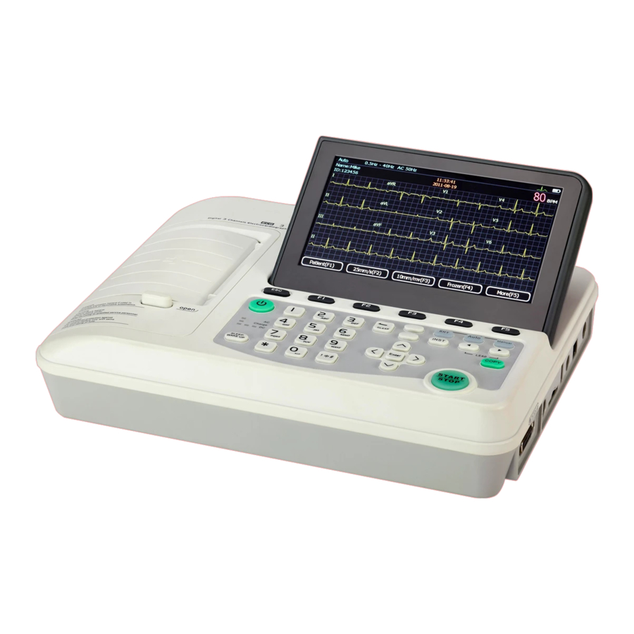
3 Structure and principle 3.1 Product structure 3.1.1Top view Sign Name Description Recorder Load recording paper, print ECG report LCD screen Display operation interface and contents Keyboard Function buttons, input of numbers and letters The LCD screen can be damaged if place heavy object on it or hit it. Please fold the screen to prevent accidental damage after use. - Page 17 3.1.2 Bottom Panel Signal Name Function description Battery compartment Lithium battery installed inside Battery label Battery group label Vents Internal heat dissipation channel Product label Product information label Fuse label Fuse specification label Fuse compartment AC fuse installation 1)Battery compartment The rated output voltage and capacity of built-in rechargeable lithium batteries are as follow: Rated output voltage: 14.8V Rated capacity: 4400mAh...
- Page 18 Sign Name Function description AC power socket Connect with AC power cord Vents Internal cooling channels Handle Easy to carry 3.1.4 Side view Sign Name Function description Patient cable socket Connect patient cable. Test interface Testing by manufacturer SD card slot For SD card insert Standard USB 2.0 port to connect external printer USB Slave Port...
- Page 19 3.1.5 Keyboard and its functions Sign Button name Function description Numbers and letters input Enter numbers, letters and signs Cancel operation Function buttons Select screen menu functions Backspace Delete the character to the left of the cursor Input method Choose the input methods: English / Numbers Five-way navigation buttons Up, down, left, right and action.
- Page 20 rhythm. Lead Select Lead switch in manual mode. START/STOP Start and stop print System enters sleep mode or back to work Sleep/wake up mode 3.1.6 Patient Cable Socket and definition for plug pins Applied part of type CF with defibrillator proof Definition of corresponding pins:...
-
Page 21: Electrodes Connection
and 4 limb lead wires. The user can identify them through the colors and the identifiers on the connectors. 3.1.8 Chest electrodes Suction Bulb Electrode Suction Cup 3.1.9 Limb electrodes (clamp style) Electrode Clamp Spring Clamp 3.2 Electrodes connection The installation of electrodes is critical for accurate record of ECG signals. Please ensure electrodes are well-connected. - Page 22 Limb electrodes should be installed on the soft skin of hands and legs. Clean the skin where electrodes will be installed with medical alcohol; Apply a small amount of electrode gel on the skin. The connection is shown in the following figure: The location for Limb electrodes are: R (RA) connect right hand L (LA) connect left hand...
-
Page 23: Patient Cable Connection
Electrode Electrode Position Electrode identifier Lead wire color color code Right arm Grey Left arm Yellow Grey Right foot Black Grey Left foot Grey Green White Yellow White Green White Chest Brown White Black White Purple White 3.2.4 Lead method and system diagram 3.3 Patient cable connection Plug the patient cable connector into the socket on the right side of ECG machine as shown... -
Page 24: Power Connection
below, and lock the screw on both sides. Patient Cable Patient Cable Socket Only use the designated patient cables. Do not use any other models. Patient cables socket is designed for ECG signal input only. Do not use it for other Purpose The instrument has built-in defibrillator protection circuit with supporting non defibrillation protection cables... -
Page 25: Principle And Schematic Diagram
Connect one end of the grounding cable to the instrument’s potential equalization and connect the other end to the ground. It can enhance the reliability of ground connection .It is forbidden to use water pipe or other pipes as grounding cable. Otherwise, the first-class safety protection will fail and patients may get electric shock. -
Page 26: Features
3.6 Features Three operating modes: Automatic, Manual and Rhythm; AC/ DC Power supply Multiple language options, convenient and flexible system setting and data management Simultaneous 12 leads ECG acquisition, amplification, display and recording; ECG analysis software can analyze ECG reports and data according to 5 judgment types and 241 cases. Built-in 4G SD card, save up to 10,000 groups of 12 leads ECG waveforms every 10sec., which can be transmitted to PC by connecting USB network interface. -
Page 27: Lead Off Indication
To ensure the patient safety and ECG reliability, please check the above and start operation. 4.4 Lead off indication The instrument constantly checks the lead connection status. If the instrument detects the lead off, it will display the corresponding information on the LCD screen as shown below, it shows C3 and C6 lead off. -
Page 28: Battery Installation
(as Picture C) 3. Tidy the leads, and 4. Close the battery cover and screw it tightly clockwise. (As picture D) 4.6 Recording paper EM-301: 80mm width*20M thermal rolled paper EM-601: 110mm width*20M thermal rolled paper... -
Page 29: Loading Recording Paper
4.7 Loading recording paper 1) Press the Open Button to open the paper compartment cover according to the arrow shown in the figure. 2) Take out the paper rollers from the paper compartment. Insert the rollers into the rolled paper as shown below 3)... -
Page 30: The Ecg Main Interface
“ON/OFF” key (about 3 seconds) and wait 15 seconds for system initialization. After the ECG beeps and starts working, the ECG is ready for operation. 5.1.2 Shutdown with the mains supply Press “ON/OFF” key (about 3 seconds) in the working state. After the LCD screen display is off, pull the power cord and grounding cable out. - Page 31 Identifier Name Description Select Rhythm, AUTO and Manual mode from the Operation mode keyboard Select it in the filter setup interface, refer to Chapter Baseline drift filter 5.5.6 Select it in the filter setup interface, refer to Chapter EMG filter 5.5.6 Set it in the time and date setup interface, refer to Time and date...
-
Page 32: Operation Mode
Press 【F5】in the first page, the second page will be shown as the following figure on the LCD screen: Identifier Name Description Press 【F1】to enter the lead system and rhythm lead Lead(F1) interface Display setup(F2) Press【F2】to enter display setup interface File (F3) Press【F3】to enter file management interface Press【F4】to enter system setup interface, refer to... - Page 33 Rhythm mode: under rhythm mode, users can select rhythm lead group and record its rhythm waveforms. 5.3.1 Manual Mode Under manual mode, “Manual 1”, “Manual 2”, “Manual 3” and ”Manual 6” ( “Manual 6” is applicable for EM-601 only) can be selected by pressing 【manual】button. Manual1: ECG is set to display single lead.
- Page 34 time is depend by users). If needing to pause or stop the print, just press 【START/STOP】 button. 4)During the recording, press 【Lead>】 and 【Lead<】button to switch to another lead’s recording. Manual 2 Select “Manual 2” mode by pressing 【manual】button. Users can choose any one lead in12 leads and rhythm lead to display.
- Page 35 Manual 6( For EM-601 only) Select “Manual 6” working mode by pressing 【manual】 button Users can choose any six leads to display. The display screen is shown as the following figure For detailed operation, please refer to “Manual 1” mode 5.3.2 Rhythm Mode This mode is rhythm lead record mode.
- Page 36 1) Press 【F2】 to set paper speed. Four kinds of speed are available for selection: 6.25mm/s, 12.5mm/s, 25mm/s and 50 mm/s; 2) Press 【F3】 to set sensitivity . Four kinds of sensitivity are available for selection: 2.5mm/mV, 5mm/mV, 10mm/mV and 20mm/mV; 3) When waveforms become stable, press 【Start/Stop】for recording, and the record length is 0~60 seconds, the ECG rhythm lead waveform with rhythm analysis will printed out.
- Page 37 3) After waveforms become stable, press 【START/STOP】button to start printing records (record time is depend on Users control). If needing to pause or stop the print, just press 【START/STOP】button. 3CH×4+1R format Detailed operation, please refer to “3×4 format” 3CH×4+3R format Detailed operation, please refer to “3×4 format”...
- Page 38 6CH×2 format Detailed operation, please refer to “3×4 format”. 6CH×2+1R format Detailed operation, please refer to “3×4 format”. 12CH×1 format Detailed operation, please refer to “3×4 format”...
-
Page 39: Leads Setup
5.4 Leads setup On the second page of main interface,press 【F1】button to enter lead setup interface. There are 8 lead systems for selection. For lead rhythm, you can choose either single lead or 3 lead rhythms as shown below. There are 8 lead setup systems available for selection. Users can select required lead system through button. -
Page 40: Display Setup
Three lead rhythms: Users can set any 3 leads as lead rhythms in the 12 leads. Under auto mode, if 3CH×4+3R is selected, the lead rhythm recorded as the rhythm leads set here. When lead selection finished, press 【F1】 button to save and return, or press 【F2】 button to cancel setup and return. -
Page 41: System Setting
5.6 System setting On the second page of the main interface, press 【F4】 to enter system setup interface. The interface is shown as the figure below: Press 【F1】 button to save system setting and return, press 【F3】 button to cancel setting and return, or press 【F2】... - Page 42 5.6.1 Management Setup 5.6.2 Print setup Press button【1】to enter print setup interface in the system setup interface. The interface is shown as the figure below: At the print setup interface, use 【▲】 and 【 ▼】 button to select setting items among Printer, Record order and ECG grids print, and then use to set Printer: Thermal Printer, Laser Printer and Ink Printer.
- Page 43 Press 【F1】 button to save print setup and return, or press 【F2】 button to cancel and return. 5.6.3 Auto analysis setup Press button【2】to enter auto analysis setup at the system setup interface. The interface is shown as below: In auto analysis setup interface, use 【▲】 and 【▼】 button to select setting items among “ ECG auto classification”, “ECG auto analysis function”, “ECG measurement”, “Auto analysis results confirmation “and ”...
- Page 44 number keys and letter keys to set and input. Press 【F1】 button to save communication setup and return, or press 【F2】 button to cancel and return. 5.6.5 Information setup Press button 【4】to enter information setup in the system setup interface. The interface is shown as below: At the information setup interface, use 【▲】and【▼】button to select setting items, and use number keys and letter keys to select and input.
- Page 45 After administrator setup, press 【F1】 button to save and return, or press 【F2】 button to cancel and return. 5.6.7 Filter setup Press button【6】to enter filter setup at the system setup interface. The interface is shown as figure below: In the filter setup interface, use 【▲】and【▼】button to select setting times among “AC filter”, “Baseline drift filter”...
- Page 46 At the time and date setup interface, use 【▲】and【▼】button to select setting items of “date format”, “date”, “time format” and “time”, and use button and number key to set and input. Date/Time: users can set current date and time. Date and time will be displayed on the main User interface;...
- Page 47 File Transmit: transmit the file via Network. Delete, Delete the patient data selected Print, print the file selected. Preview, preview the patient file selected Press more to next page Edit: Edit the patient information here, it is able to edit the name, ID etc. Query, query the patient data by ID, Name, Sex, Age, time.
- Page 48 Replay Press F4 to Freeze the waveform displayed on the main interface. Press MORE to next page. It is able to freeze up to 120 seconds ECG waveform, 10 seconds ECG waveform at least.(the figure showed above is the data freeze for 10 seconds, ECG waveform is displayed from the 3 second.) Pre Sec: Display from previous second.
-
Page 49: Cleaning, Disinfection And Maintenance
6 Cleaning, Disinfection and Maintenance 6.1 Cleaning Turn off the ECG and remove the patient cable. Unplug the power cord from the AC outlet if main supply applied. 1) Cleaning the main unit and patient cable Wipe the exterior of the main unit and patient cable with a damp cloth using mild (non-caustic neutral) detergent diluted in water. -
Page 50: Care And Maintenance
Before using the rechargeable lithium battery, read the operation manual carefully. 1) Charge ECGMAC ECG is equipped with recharge control circuit together with built-in rechargeable lithium battery. Because of the capacity consumption during storage and transport, the capacity of battery is not full while using the first time. - Page 51 Danger of explosion— Do not reverse the anode and cathode when connecting the battery Only authorized maintenance engineers can open the battery compartment and replace the battery. Only the battery of same model and specification provided by manufacturer should be used Battery has to be disposed and recycled according to the local regulation.
-
Page 52: Common Troubleshooting And Solution
If the same model fuse is broken again after changing the fuse, it might indicate other failure in the instrument. In this condition, turn off the machine and contact the maintenance agent designated by ECGMAC. 7 Common troubleshooting and solution 7.1 Some lead without waveform printout... -
Page 53: Buttons On The Control Panel Not Working
7.3 Buttons on the control panel not working Possible reason: The control panel and circuit board are not well connected due to the vibration in transportation. Solution: Open the instrument cover and connect them again, if the problem still exists, contact with our after sale service department or appointed maintenance center. 7.4 AC interference AC interference is interference which arises from super positioning of ECG wanted signal with sinusoidal voltages with the mains frequency. -
Page 54: Baseline Drift
Solutions: Move to a comfortable room if the room is uncomfortable Let the patient to be relaxed Make sure the bed is not too small. The patient should keep quiet Change the limb electrodes if it is too tight. If the EMG interference still exists, please apply EMG filter .The waveform will be weakened a little and have obvious effect for the weakening of R wave. -
Page 55: Warranty And After-Sale Service
ECGMAC will, at its discretion, repair or replace the defective part(s) free of charge. ECGMAC will not provide a substitute product for use when the defective product is being repaired. -
Page 56: Appendix A Packaging And Accessories
3) If the package does not match the packaging list or the instrument does not work properly, contact the sales department or customer service department; 4) Please use the accessories supplied by ECGMAC. Accessories from other suppliers may damage the instrument and affect its performance and safety. Before using the accessories from other suppliers, please consult our customer service first;... -
Page 57: Appendix B Product Performance
Appendix B Product Performance B.1 External Output 1.1 Sensitivity 1V/mV,Tolerance:±5% or 0.5V/mV. 1.2 Impedance of External Output ≤100Ω. 1.3 Output short circuit shall not damage the ECG machine. B.2 External DC signal Input 1.4 Sensitivity 10mm/V. Tolerance:±5% 1.5 Input Impedance ≥100kΩ 1.6 Input Impedance Attenuation. - Page 58 Table 1 Input Impedance The summit vlaue of deflectionfront Lead Electrode Lead Position traced by K open circuit (mm) Connecting to P1 Connecting to P2 Single Channel ECG Multi-channel ECG Ⅰ,Ⅱ,aVR, aVL, All other Lead electrodes aVF,V1 Ⅰ,Ⅲ,aVL, aVR, All other Lead electrodes aVF,V2 Ⅱ,Ⅲ,aVF, aVR,...
-
Page 59: Appendix C Specification
The range of voltage input 1.20 Each lead should no less than 0.03 to 5mV and the waveform should be correct. Tolerance of Weighted parameters 1.21 Should be no more than ±10%。 Waveform identification and amplitude-time parameters measurement 1.22 Should match with the waveform shown in A.1,A.2 and A.3 in appendix JJG 1041-2008. The testing result comply with the value range of A.1.1~A.1.4,A.2.1~A.2.2 in appendix JJG 1041-2008. - Page 60 Resolution ≥ 32 dots/mm (25 mm/s) ; ≥16 dots/m (50 mm/s) (Horizontal) Recording Paper EM-601: 110mm width rolling paper EM-301: 80mm width rolling paper 3) Display Display 7 inches color LCD screen, display resolution: : 800×480 Paper Out, Lead Off Alarm, Operation Manual, Patient Information,...
-
Page 61: Dimension And Weight
C.2 Dimension and weight Dimension 310mm×244mm×65mm Package Size 380 mm×330 mm×230mm Net weight 2.25KGS Gross weight 4.1KGS C.3 Environment conditions Transportation Temperature -20℃~+50℃ Relative humidity 25%~95% (Non-condensing) Atmospheric pressure 500hPa~1060hPa Storage Temperature -20℃~+50℃ Relative humidity 25%~85% Atmospheric pressure 500hPa~1060hPa Usage Temperature +5℃~+40℃... - Page 62 IEC 60601-1-2:2001+A1:2004 EN 60601-1-2:2007 Medical electrical equipment -- Part 1-2: General requirements for basic safety and essential performance - Collateral standard: Electromagnetic compatibility - Requirements and tests IEC 60601-1-2:2007 (Modified) EN 60601-1-4:1996+A1:1999 Medical electrical equipment -- Part 1-4: General requirements for safety - Collateral standard: Programmable electrical medical systems IEC 60601-1-4:1996 +A1:1999...
-
Page 63: Appendix E Emc Information
EMC guidance and manufacturer’s declarations - Electromagnetic emissions EM-301 electrocardiograph is intended for use in the electromagnetic environment specified below. The customer or user of EM-301electrocardiograph should assure that it is used in such an environment. Emissions test... - Page 64 Note:U AC voltage before test voltage is applied EMC guidance and manufacturer’s declarations –Electromagnetic immunity – For non-life-support equipment EMC guidance and manufacturer’s declarations –Electromagnetic immunity EM-301、EM-601 electrocardiograph is intended for use in the electromagnetic environment specified below. Immunity test IEC 60601...
- Page 65 EM-301、EM-601 electrocardiograph EM-301、EM-601 electrocardiograph s intended for use in an electromagnetic environment in which radiated RF disturbances are controlled. The customer or user of EM-301、EM-601 electrocardiograph can help prevent electromagnetic interference by maintaining a minimum distance between portable and mobile RF communications equipment (transmitters) and EM-301、EM-601 electrocardiograph h as recommended...
-
Page 66: Appendix F Manufacturer Information
Note 2: These guidelines may not apply in all situations. Electromagnetic propagation is affected by absorption and reflection from structures, objects, and people. Appendix F Manufacturer information Manufacturer: Shenzhen ECGMAC Medical Electronics Co., Ltd Factory Address: 2nd Floor of Block 2, Haoye Industrial Park, Tiegang Road,Xixiang Street, Baoan District, 518102 Shenzhen,China...
Need help?
Do you have a question about the EM-301 and is the answer not in the manual?
Questions and answers