Table of Contents
Advertisement
Copyright ©2014 Shenzhen ECGMAC Medical Electronics Co., Ltd. All rights reserved.
Statement
Shenzhen ECGMAC Medical Electronics Co., Ltd (hereinafter called ECGMAC) assumes no
responsibility for any injury, or for any improper or illegal use of the product, that results from
failing to comply with this manual, ECGMAC assumes no consequence caused by the publication.
Any part of the manual shall not be reproduced, photocopied in any form without prior written
permission from ECGMAC.ECGMAC reserves the right to change, update, revise the product
design, specification or function at any time without notice.
Responsibility of the Manufacturer
ECGMAC only considers itself responsible for any effects on safety, reliability and performance of
the equipment if:
Assembly operations, extensions, re-adjustments, modifications or repairs are carried out by
personnel authorized by ECGMAC, and the electrical installation of the relevant room complies
with safety standards.
1
Advertisement
Table of Contents

Related Manuals for ECGMAC EM-1203


Summary of Contents for ECGMAC EM-1203
- Page 1 ECGMAC assumes no consequence caused by the publication. Any part of the manual shall not be reproduced, photocopied in any form without prior written permission from ECGMAC.ECGMAC reserves the right to change, update, revise the product...
-
Page 3: Table Of Contents
CONTENTS 1 Safety Guidance......................5 1.1 Installation and Storage ..........................5 1.2 Before Operation ............................5 1.3 During Operation ............................5 1.4 After Operation............................6 1.5 EMC and Relevant Notes ..........................6 1.6 Device Classification ........................... 6 1.7 Measurement Requirement.......................... 7 1.8 Discarding the Equipment ........................... - Page 4 5.6 Operation Mode ............................33 5.7Leads Setup..............................40 5.8 Display Setup............................. 41 5.9 System Setting ............................42 6 Cleaning, Disinfection and Maintenance ..............48 6.1 Cleaning..............................48 6.2 Disinfection ............................... 49 6.3 Care and Maintenance ..........................49 6.4 Fuse Exchange ............................51 7 Common Troubleshooting and Solution ..............
-
Page 5: Safety Guidance
1 Safety Guidance This is provided for the use of qualified physicians or personnel professionally trained. The operator is supposed to be familiar with the contents of this Operation Manual before operation. This is applicable for ECG signal acquisition, recording and analysis. 1.1 Installation and Storage Avoid contact with water. -
Page 6: After Operation
1.4 After Operation Reset all the function setup to the initial state and shut down the power; Gently remove the electrodes, and do not harshly drag the wires; Clean the instrument and accessories for the later use. 1.5 EMC and Relevant Notes This instrument complies with IEC60601-1-2 standard about the medical electronic equipment safety standards on electromagnetic compatibility. -
Page 7: Measurement Requirement
To guarantee the record quality of the ECG waveforms, please use the high speed thermal paper supplied or appointed by ECGMAC. Other paper may shorten print head’s life. And the deteriorated print head may lead to illegible ECG record and block the advance of paper etc Please do pay attention to the following aspects:... -
Page 8: Symbols
1.10 Symbols Function Symbols Function Symbols Alternating current Battery recharging indicator Product serial number Manufacturer Date of manufacture Recycle Storage temperature range Avoid direct light Keep dry Equipment of type CF with Tier limitation defibrillator proof Note (general warning): the information you should know to Battery indicator avoid possible damage to patients... -
Page 9: Safety Information
Only qualified service engineers can install this equipment. And only service engineers authorized by ECGMAC can open the shell case. Auxiliary equipments connected to the digital and analog interfaces must be certified according to IEC standards (e.g. IEC950 for data processing equipment and IEC60601-1 for medical equipment). -
Page 10: Warnings For Rechargeable Lithium Battery
The operator should not touch patient, patient bed, table or instrument when it use simultaneous with the defibrillator or pacemaker. Please use the patient cable and other accessories supplied by ECGMAC. Otherwise, it will affect the performance and function, even damage the ECG. -
Page 11: General Notes
manufacturer should be used. When the shelf life of battery is due, or foul smell and leakage has been found, stop using it, and contact the manufacturer or local distributor for disposal or dispose the battery according to local regulations. Do not pull in or take out the battery when the equipment is powered on, which will cause white screen, crash, etc. -
Page 12: Cleaning, Disinfection And Maintenance
Electrical schematic diagram and parts lists are only available to qualified repair stations or staff of ECGMAC authorized. 2.5 Intended Use The intended use is to acquire the ECG waveforms from adults and children patients through electrodes. -
Page 13: Contraindication
ECG with the measured value and its explanatory notes are only for the reference of clinicians. 2.6 Contraindication Absolute Contraindication 1. Acute myocardial infarction (within 2days) 2. High risk unstable angina 3. Hemodynamic disorder caused by uncontrolled arrhythmia 4. Active endocarditis 5. -
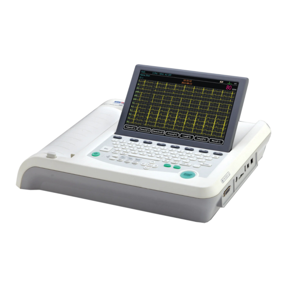
Page 14: Structure And Principle
3 Structure and Principle 3.1 Product Structure It mainly consists of main unit and patient cable. 3.1.1Top View EM-1201 Top view EM-1202&1203 Top view... - Page 15 Sign Name Description Recorder Load recording paper, print ECG report LCD screen Display operation interface and contents Keyboard Function buttons, input of numbers and letters The LCD screen can be damaged if place heavy object on it or hit it. Please fold the screen to prevent accidental damage after use.
- Page 16 3.1.3 Rear View Sign Name Function description AC power socket Connect with AC power cord The equipotential stud is used for connecting with the Equipotential stud grounding line when equipotential grounding line is needed for electronic safety Handle Portable to carry Vents Internal cooling channels 3.1.4 Side View...
- Page 17 Test interface B list above is for manufacturer use only 3.1.5 Keyboard and Its Functions Sign Button name Function description ON/OFF Power on/ Power off Cancel operation Function keys Select menu functions on the screen CLEAR/Del Delete the character Enter Confirm the operation When using Z-fold paper and enable Paper Marker, press the tab key to advance the recording paper to...
- Page 18 Reserved buttons for future use Reserved buttons for stress test function ( for Reserved buttons for stress test EM-1202& EM-1203 only) 3.1.6 Patient Cable Socket and Definition for Plug Pins Applied part of type CF with defibrillator proof Definition of corresponding pins:...
-
Page 19: Electrodes Connection
limb lead wires. The user can identify them through the colors and the identifiers on the connectors. 3.1.8 Chest Electrodes Suction Ball Electrode Suction Cup 3.1.9 Limb Electrodes (clamp style) Electrode Clamp Spring Clamp 3.2 Electrodes Connection The installation of electrodes is critical for accurate record of ECG signals. Please ensure electrodes are well-connected. - Page 20 F (LL) connect left leg 3.2.2 Chest Electrodes Connection Clean the skin where electrodes will be connected with alcohol; Apply about 25mm diameter electrode gel on the skin where the electrodes contacted; Apply a small amount of electrode gel on the edge of the sucker ball of the chest electrodes;...
-
Page 21: Patient Cable Connection
Green White Brown White Black White Purple White 3.2.4 Lead Method and System Diagram 3.3 Patient Cable Connection Plug the patient cable connector into the socket on the right side of ECG machine as shown below, and lock the screw on both sides. Patient Cable Socket Patient Cable Only use the designated patient cables. -
Page 22: Power Connection
3.4 Power Connection 3.4.1 AC Power Connection and Grounding Cable Connection Plug one end of three-core power cord to the power socket on the ECG and the other end to the socket on the wall as shown below: 3.4.2 DC Battery The battery is not put into the battery compartment when it is dispatched with the machine, it needs installation after receive it. -
Page 23: Schematic Diagram
High-resolution thermal matrix printing system, recording frequency response is not more than 150Hz, Big keyboard with independent numeric key, big printing key; 12 inch color LCD for EM-1203 ( 10 inch color LCD for EM-1202, EM-1201) 4 Operation Preparations 4.1 Applicable Fields The Electrocardiographs are applicable for hospitals, clinics, group checkup and other outdoor activities. -
Page 24: Environmental Operating Conditions
4.2 Environmental Operating Conditions Please make sure the temperature and humidity meet the requirement for use. ~40 Temperature 5 ℃ ℃ Relative humidity 25%~95% 4.3 Inspection before Operation Check if the instrument, socket and grounding cable are well connected. Confirm no high voltage cable, X ray, ultrasonic, electrosurgical machine and other high power equipment around the instrument. -
Page 25: Battery Installation
reconnect them. 1)Electrodes fall off ① When the lead wires are not connected to the patient or the instrument stably, ECG signals can not be transmitted correctly, this message will be displayed for reminding; ② When the polarization voltage exceeds the limit value, the message will be displayed for reminding. -
Page 26: Loading Recording Paper
4. Close the battery cover and screw it tightly clockwise. (As picture D) 4.6 Loading Recording Paper Two kinds of thermal paper can be used. One is Z-fold thermal paper; the other one is rolled thermal paper. (Note: when using the Z-fold thermal paper, the paper roller should be taken out) Loading Roll Paper The applied width for the recording paper is 216 mm, load the paper according to following steps. -
Page 27: Operation Instructions
Make sure that the recorder paper is installed in the center of the recorder, and the paper edge is parallel with the casing edge in the direction of paper, in order to avoid paper deviation or damage to the paper edge. Loading Z-fold paper: 1) Press the casing button and take out the paper roller 2) Put the paper in the paper tray... -
Page 28: Shutdown With The Mains Supply
5.2 Shutdown with the Mains Supply Press “ON/OFF” key (about 3 seconds) in the working state. After the LCD screen display is off, pull the power cord and grounding cable out. 5.3 Startup and Shutdown with the Battery When power cord is disconnected, the ECG will use the built-in battery. And the DC indicator is lit. Then the same startup and shutdown operation with the mains supply. - Page 29 Identifier Name Description Operation Mode Select Rhythm, AUTO and Manual mode from the keyboard Baseline Drift Filter Select it in the filter setup interface, refer to Chapter 5.9.7 EMG filter Select it in the filter setup interface, refer to Chapter 5.9.7 Time and date Set it in the time and date setup interface, refer to Chapter 5.9 Power supply mode...
- Page 30 Press F7 “More” to enter the next page. It is able to freeze up to 120 seconds ECG waveform, 10 seconds ECG waveform at least. (The figure showed above is the data freezing for 10 seconds; ECG waveform is displayed from the 3 second.) Pre Sec: Display from previous second.
- Page 31 Identifier Name Description Display Press【F1】to enter display setup interface, refer to Chapter 5.8 File Press【F2】to enter file management interface More Press【F7】to return to the first page of the main interface File Press 【F2】to enter file management interface. Identifier Name Description Press 【F1】to transmit the file to PC via FTP upload Transmit Press【F2】to delete the selected file...
- Page 32 Preview Press 【F3】to replay the waveforms of selected file Press 【F3】to edit the patient information of selected file Edit Press 【F6】 to query the patient data by ID, Name, Sex, Age and Query check time Exit Press【F7】to exit current menu Edit: Edit the patient information here;...
-
Page 33: Operation Mode
5.6 Operation Mode This ECG has three operation modes: Manual mode, AUTO mode and Rhythm mode. Users can press【Manual】,【Auto】or【RHY】button to select. Manual mode: under manual mode, users can select lead group need to be recorded. When the users need to record another ECG lead group, manual switch is required. AUTO mode: under auto mode, the lead groups switch automatically. - Page 34 Select “Manual 1” mode by pressing 【manual】 button. Users can select one lead in 12 leads to display. The display interface is shown as the below: When the main interface is displayed, press F1 Patient to enter the Patient Information interface. 1) Press F2 to set paper speed, 5mm/s, 6.25 mm/s, 10mm/s, 12.5 mm/s, 25 mm/s, 50 mm/s are available to select.
- Page 35 For detailed operation, please refer to “Manual 1” mode. Manual 3 Select “Manual 3” mode by pressing 【manual】button. Users can choose any three leads in 12 leads to display. The display screen is shown as the following figure. For detailed operation, please refer to “Manual 1” mode. Manual 6 Select “Manual 6”...
- Page 36 For detailed operation, please refer to “Manual 1” mode. Manual 12 Manual 12, for detailed operation, please refer to “Manual 1” mode 5.6.2 Rhythm Mode This mode is rhythm lead record mode. The ECG signal acquisition duration for selected rhythm is 60seconds, it start print after the 60seconds’...
- Page 37 Rhythm1 Rhythm3 1) Press 【F2】 to set paper speed. Four kinds of speed are available for selection: 5mm/s, 6.25mm/s, 10mm/s, 12.5mm/s, 25mm/s and 50 mm/s; 2) Press 【F3】 to set gain . Four kinds of sensitivity are available for selection: 2.5mm/mV, 5mm/mV, 10mm/mV and 20mm/mV;...
- Page 38 3CH×4 3 rows ×4 columns 3CH×4+1R 3 rows ×4 columns+ 1 rhythm lead 3CH×4+3R 3 rows×4 columns+ 3 rhythm leads 6CH×2 6 rows×2 columns 6CH×2+1R 6 rows×2 columns+1 rhythm lead 12CH×1 12 rows×1 column 3CH×4 format 1) Press 【F1】 to enter patient information interface for input the patient information. 2) Press 【F2】to set paper speed: 5mm/s, 6.25mm/s, 10mm/s, 12.5mm/s, 25mm/s and 50 mm/s available;...
- Page 39 Detailed operation, please refer to “3CH×4 format” 3CH×4+3R format Detailed operation, please refer to “3CH×4 format” 6CH×2 format...
-
Page 40: Leads Setup
Detailed operation, please refer to “3CH×4 format” 6CH×2+1R format Detailed operation, please refer to “3CH×4 format”. 12CH×1 format Detailed operation, please refer to “3CH×4 format” 5.7 Leads Setup On the second page of main interface, press 【F6】 “setup” button to enter system setting, press 【8】 “Lead selection”... -
Page 41: Display Setup
There are eight lead systems for user chose, press to switch the lead system. Users can set single lead rhythm and three lead rhythms here. Select any lead rhythm from the 12 leads by pressing 【▲】and【▼】button. Single lead rhythm: Users can set any single lead as lead rhythm. In auto mode, if 3×4+1R or 6×2+1R are selected, the single lead rhythm displayed is the lead set here. -
Page 42: System Setting
through 【▲】and【▼】button. After selecting the setting item, use button to choose setting contents There are 6 display formats as following: 3×4, 3×4+1R, 3×4+3R, 6×2, 6×2+1R and 12×1. 3×4 12 leads ECG waveform display with 3rows ×4 columns 3×4+1R 12 leads ECG waveform display with 3rows ×4 columns+ 1 rhythm lead 3×4+3R 12 leads ECG waveform display with 3 rows×4 columns+ 3 rhythm leads 6×2... - Page 43 Print setup 【1】 Auto analysis setup 【2】 Communication setup 【3】 Information setup 【4】 Administrator setup 【5】 Filter 【6】 Time and date 【7】 Lead setup 【8】 Others 【9】 5.9.1 Management Setup 5.9.2 Print Setup Press button 【 1】 to enter print setup interface in the system setup interface. The interface is shown as the figure below:...
- Page 44 At the print setup interface, use 【▲】 and 【▼】 button to select Printer, Record order and ECG grids print, use to set. Printer: Thermal Printer, Laser Printer and Ink Printer. Print Direction can be selected as horizontal or vertical when machine connecting to USB printer with PCL6 language, the printout will be in horizontal when set as horizontal.
- Page 45 confirmation “and ” Heart rate range”. Use to “enable” and “disable”. Press 【F1】 button to save auto analysis setup and return, or press 【F2】 button to cancel and return. 5.9.4 Communication Setup Press【3】to enter communication setup in the system setup interface. The interface is shown as figure below: At the communication setup interface, use 【▲】and【▼】button to select setting items, and use number keys and letter keys to set and input.
- Page 46 At the information setup interface, use 【▲】and【▼】button to select setting items, and use number keys and letter keys to select and input. Press 【F1】 button to save information setup and return, or press 【F2】 button to cancel and return. 5.9.6 Admin Configuration Press button 【...
- Page 47 “Baseline drift filter” and “EMG Filter” , use to set. AC filter: OFF/ 50Hz/ 60Hz Baseline Drift Filter: OFF/ 0.05Hz/ 0.15Hz/ 0.25Hz/ 0.32Hz/ 0.5Hz/ 0.67Hz/ ADS; EMC Filter: OFF/ 40Hz/ 30 Hz/ 25 Hz Low Pass Filter: OFF/ 75Hz/ 100Hz/ 150Hz Press 【F1】...
-
Page 48: Cleaning, Disinfection And Maintenance
At the other function setup interface, use 【▲】and【▼】button to select setting items among “keypad tone”, “Beep volume”, “QRS Beep”, “Power-save” and “LCD backlight off time”, and use button and number key to select and input. If user wants to keep the LCD backlight always on or disable power-save function, set the value as 0. -
Page 49: Disinfection
Before using the rechargeable lithium battery, read the operation manual carefully. 1) Charge ECGMAC ECG is equipped with recharge control circuit together with built-in rechargeable lithium battery. Because of the capacity consumption during storage and transport, the capacity of battery is not full while using the first time. - Page 50 Battery is full Battery is sufficient Battery is low. Need charging Battery is not sufficient. Need charging Battery is completely empty. Need charging immediately. 3) Replacement When the battery’s useful life is over, or foul smell and leakage has been found, please contact with the manufacturer or local distributor for replacement of battery Danger of explosion, do not reverse the anode and cathode when connecting the battery Only authorized maintenance engineers can open the battery compartment and replace the...
-
Page 51: Fuse Exchange
If the same model fuse is broken again after changing the fuse, it might indicate other failure in the instrument. In this condition, turn off the machine and contact the maintenance agent designated by ECGMAC. 7 Common Troubleshooting and Solution 7.1 Some Lead without Waveform Printout... -
Page 52: Vertical Breakpoint Of Printed Waveform
Solution: repeat operation. There is failure with patient cable. Check the patient cable by the methods in chapter 7.3.3. Contact our after-sale service department or appointed maintenance center if it is broken. If the instrument still has this problem, normally the problem is caused by the signal channel failure, contacts our after-sale service department or appointed maintenance center. -
Page 53: Emg Interference
The metal bed is properly grounded Keep the patient from physical contact with the surroundings. There is no powerful equipment operating nearby, such as X ray or ultrasonic machine The patient don’t wears jewelry such as glass or gem If interference still exists, please reset AC filter according to local AC frequency 7.5 EMG Interference Phenomenon: Recorded ECG base line has irregular vibration, as shown in the following ECG waveforms. -
Page 54: Warranty And After-Sale Service
ECGMAC will, at its discretion, repair or replace the defective part(s) free of charge. ECGMAC will not provide a substitute product for use when the defective product is being repaired. -
Page 55: Appendix A Packaging And Accessories
3) If the package does not match the packaging list or the instrument does not work properly, contact the sales department or customer service department; 4) Please use the accessories supplied by ECGMAC. Accessories from other suppliers may damage the instrument and affect its performance and safety. Before using the accessories from other suppliers, please consult our customer service first;... -
Page 56: Appendix B Product Performance
Appendix B Product Performance B.1 External Output Sensitivity 1V/mV,Tolerance:±5% or 0.5V/mV. Impedance of External Output ≤100Ω. Output short circuit shall not damage the ECG machine. B.2 External DC signal Input 2.1 Sensitivity 10mm/V. Tolerance:±5% 2.2 Input Impedance ≥100kΩ 2.3 Input Impedance Attenuation. By Paralleling impedance of 4700PF capacitor and 620KΩ is connected to each lead electrode. - Page 57 amplitude should be less than 10mm 2.9 50Hz Anti-interference filter ≥20dB Table1 Input Impedance The summit value of deflection front Lead Electrode traced by K open circuit (mm) Lead Position Connecting Connecting to Single Channel ECG Multi-channel ECG to P1 Ⅰ,Ⅱ,aVR, aVL, All other Lead electrodes...
-
Page 58: Appendix C Specification
Y axis ≥8 dots/mm; X axis ≥32 dots/mm(Paper speed 25 mm/s)≥16 dots/mm(Paper speed 50 mm/s). 2.17 Request of Thermal matrix printing Printer can record letters and marks. When recording, the printer could print out lead, paper speed, gain and etc. 2.18 The range of voltage input Each lead should no less than 0.03 to 5mV and the waveform should be correct. -
Page 59: Dimension And Weight
Roll Paper: 216mm*30M Z fold Paper: 216mm*295mm*100P 3) Display Display 12 inch color LCD screen, display resolution: : 800×600 (EM-1203) 10 inch color LCD screen, display resolution: : 800×480 (EM-1201& EM-1202) Paper Out, Lead Off Alarm, Operation Manual, Patient Information,... -
Page 60: Environment Conditions
EMC guidance and manufacturer’s declarations - Electromagnetic emissions EM-1201/1202/1203 ECG Machine are intended for use in the electromagnetic environment specified below. The customer or user of EM-1203/1202 electrocardiograph should assure that it is used in such an environment. Emissions test... - Page 61 Complies Voltage fluctuations/ flicker emissions IEC 61000-3-3 EMC guidance and manufacturer’s declarations - Electromagnetic emissions - For all the equipments and systems EMC guidance and manufacturer’s declarations –Electromagnetic immunity EM-1201/1202/1203 ECG Machine are intended for use in the electromagnetic environment specified below.
- Page 62 for 5 sec for 5 sec Note:U is the a.c. mains voltage prior to application of the test level. EMC guidance and manufacturer’s declarations –Electromagnetic immunity – For non-life-support equipment EMC guidance and manufacturer’s declarations –Electromagnetic immunity EM-1201/1202/1203 ECG Machine are intended for use in the electromagnetic environment specified below.
- Page 63 ⎡ ⎤ 800MHz-2.5GHz ⎢ ⎣ ⎥ ⎦ Where P is the maximum output power rating of the transmitter in watts (W) according to the transmitter manufacturer and d is the recommended separation distance in metres (m). Field strengths from fixed RF transmitters, as determined by an electromagnetic site survey, should be less...
-
Page 64: Appendix E Manufacturer Information
Note 4 These guidelines may not apply in all situations. Electromagnetic propagation is affected by absorption and reflection from structures, objects and people. Appendix E Manufacturer Information Manufacturer: Shenzhen ECGMAC Medical Electronics Co., Ltd Factory Address: 2nd Floor of Block 2, Haoye Industrial Park, Tiegang Road,Xixiang Street, Baoan District, 518102 Shenzhen, China...
Need help?
Do you have a question about the EM-1203 and is the answer not in the manual?
Questions and answers