Table of Contents
Advertisement
Quick Links
Advertisement
Table of Contents

Related Manuals for ECGMAC VET-301


Summary of Contents for ECGMAC VET-301
- Page 1 User Manual VET-301 Multi-channel ECG Version: 1.0...
- Page 2 ECGMAC assumes no consequence caused by the publication. Any part of the manual shall not be reproduced, photocopied in any form without prior written permission from ECGMAC.ECGMAC reserves the right to change, update, revise the product...
-
Page 3: Table Of Contents
Contents 1. Safety Guidance......................5 1.1 Installation and Storage..........................5 1.2 Before Operation.............................5 1.3 During Operation............................5 1.4 After Operation............................... 6 1.5 EMC and Relevant Notes..........................6 1.6 Device Classification............................6 1.7 Measurement Requirement..........................7 1.8 Discarding the Equipment..........................7 1.9 Symbols................................7 1.10 Recording Paper............................8 2. - Page 4 6.1 Cleaning................................ 42 6.2 Disinfection..............................43 6.3 Care and Maintenance..........................43 7. Common Troubleshooting and Solution..............46 7.1 Some Lead without Waveform Printout....................... 46 7.2 Vertical Breakpoint of Printed Waveform....................46 7.3 Buttons on the Control Panel not Working....................47 7.4 AC Interference.............................47 7.5 EMG Interference............................
-
Page 5: Safety Guidance
1. Safety Guidance This is provided for the use of qualified physicians or personnel professionally trained. The operator is supposed to be familiar with the contents of this Operation Manual before operation. This is applicable for Veterinary ECG signal acquisition, recording and analysis. 1.1 Installation and Storage ... -
Page 6: After Operation
1.4 After Operation Reset all the function setup to the initial state and shut down the power; Gently remove the electrodes, and do not harshly drag the wires; Clean the instrument and accessories for the later use. 1.5 EMC and Relevant Notes This instrument complies with IEC60601-1-2 standard about the medical electronic equipment safety standards on electromagnetic compatibility. -
Page 7: Measurement Requirement
Combustible gas safety: Not suitable for use under the presence of flammable gas Mode of operation: Continuous 1.7 Measurement Requirement ECG belongs to measurement instrument. The users are suggested to send the instrument to authorized Measurement Institutes for verification at least once a year according to the state ECG and EEG metrological verification regulations. -
Page 8: Recording Paper
To guarantee the record quality of the ECG waveforms, please use the high speed thermal paper supplied or appointed by ECGMAC. Other paper may shorten print head’s life. And the deteriorated print head may lead to illegible ECG record and block the advance of paper etc Please do pay attention to the following aspects:... -
Page 9: Safety Information
Only qualified service engineers can install this equipment. And only service engineers authorized by ECGMAC can open the shell case. Auxiliary equipments connected to the digital and analog interfaces must be certified according to IEC standards (e.g. IEC950 for data processing equipment and IEC60601-1 for medical equipment). -
Page 10: Warnings For Rechargeable Lithium Battery
The operator should not touch animal, animal bed, table or instrument when it use simultaneous with the defibrillator or pacemaker. Please use the animal cable and other accessories supplied by ECGMAC. Otherwise, it will affect the performance and function, even damage the ECG. -
Page 11: General Notes
Improper operation might cause the rechargeable lithium battery to become hot, ignited, exploded, and it may lead to declination of battery capacity. It is necessary to read the Operation Manual carefully and pay more attention to warning messages. Danger of explosion- Do not reverse the anode and cathode when connecting the battery. Do not use the battery near fire or place over 60℃. -
Page 12: Cleaning, Disinfection And Maintenance
Avoid liquid splash and excessive temperature. The temperature must be kept between 5℃ to 40℃ while working. Do not use the equipment in dusty environment with poor ventilation or in the presence of corrosive, such as salt, sulphur and chemicals. Be sure that there is no intense electromagnetic interference source around the equipment, such as radio transmitter or mobile phone etc. -
Page 13: Intended Use
Electrical schematic diagram and parts lists are only available to qualified repair stations or staff of ECGMAC authorized. 2.5 Intended Use The intended use is to acquire the ECG waveforms from animals through electrodes. It should be used by doctors or trained nurses in medical institutions. -
Page 14: Structure And Principle
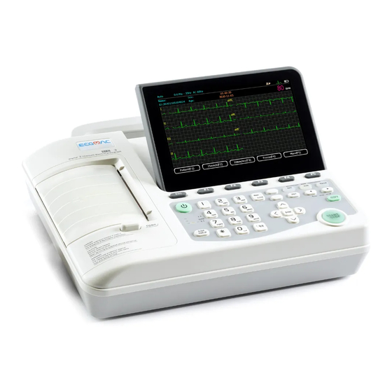
3 Structure and Principle 3.1 Product Structure 3.1.1Top view Sign Name Description Recorder Load recording paper, print ECG report LCD screen Display operation interface and contents Keyboard Function buttons, input of numbers and letters The LCD screen can be damaged if place heavy object on it or hit it. Please fold the screen to prevent accidental damage after use. - Page 15 3.1.2 Bottom Panel Signal Name Function description Battery compartment Lithium battery installed inside Battery label Battery group label Vents Internal heat dissipation channel Product label Product information label Fuse label Fuse specification label Fuse compartment AC fuse installation Battery compartment The rated output voltage and capacity of built-in rechargeable lithium batteries are as follow: Rated output voltage: 14.8V Rated capacity:2200mAh...
- Page 16 Sign Name Function description AC power socket Connect with AC power cord Vents Internal cooling channels Handle Easy to carry 3.1.4 Side view Sign Name Function description Animal cable socket Connect animal cable. Test interface Testing by manufacturer SD card slot For SD card insertion Standard USB 2.0 port to connect external printer USB Master Port...
- Page 17 3.1.5 Keyboard and the Functions Sign Button Name Function Description Numbers and letters input Enter numbers, letters and signs Cancel operation Function buttons Select screen menu functions Backspace Delete the character to the left of the cursor Input method Choose the input methods: English / Numbers Five-way navigation buttons Up, down, left, right and action.
-
Page 18: Electrodes Connection
rhythm. Lead Select Lead switch in manual mode. START/STOP Start and stop print System enters sleep mode or back to work Sleep/wake up mode 3.2 Electrodes Connection The installation of electrodes is critical for accurate record of ECG signals. Please ensure electrodes are well-connected. - Page 19 R (RA) connect right forelimb; L (LA) connect left forelimb RF (RL) connect right hind legs; F (LL) connect left hind legs 3.2.4 Lead Method and System Diagram...
-
Page 20: Animal Cable Connection
3.3 Animal Cable Connection Plug the animal cable connector into the socket on the right side of ECG machine as shown below, and lock the screw on both sides. Animal Cable Animal Cable Socket Only use the designated animal cables. Do not use any other models. animal cables socket is designed for ECG signal input only. -
Page 21: Principle And Schematic Diagram
The battery is not put into the battery compartment when it is dispatched with the machine, it needs installation after receiving it. After receiving the ECG, if built‐in rechargeable battery is to be used, check the battery capacity and condition. Connect one end of the grounding cable to the instrument’s potential equalization and connect the other end to the ground. -
Page 22: Operation Preparations
4. Operation Preparations 4.1 Applicable Fields VET-301 is applicable for hospitals, clinics, group checkup and other outdoor activities. 4.2 Inspection before Operation Check if the instrument, Socket and grounding cable are well connected. Confirm no high voltage cable, X ray, ultrasonic, electrosurgical machine and other high power equipment around the instrument. -
Page 23: Battery Installation
When lead off, the waveform will not be displayed. Pressing "record" button is ineffective. Please check the loose electrodes or electrode leads according to the prompt message and reconnect them. 1)Electrodes fall off ① When the lead wires are not connected to the animal or the instrument stably, ECG signals can not be transmitted correctly, this message will be displayed for reminding;... -
Page 24: Recording Paper
4. Close the battery cover and screw it tightly clockwise. (As picture D) 4.5 Recording Paper VET-301: 80mm width×20M thermal rolled paper 4.6 Loading Recording Paper 1) Press the Open Button to open the paper compartment cover according to the arrow shown in the figure. -
Page 25: Operation Instructions
3) As shown in the figure below, put the paper with rollers back into the paper compartment. After that, pull about 2cm of the paper out and close the cover. 5. Operation Instructions 5.1 Startup and Shutdown 5.1.1 Startup with the Main Supply When power cord and grounding cable are well connected, and the AC supply indicator is lit. -
Page 26: The Ecg Main Interface
5.2 The ECG Main Interface Press “ON/OFF” key (about 3 seconds) to turn on. After system initialization, the first page of the main interface will be shown as the following figure: Identifier Name Description Select Rhythm, AUTO and Manual mode from the Operation mode keyboard Baseline drift filter... - Page 27 10mm/s, 12.5mm/s, 25mm/s, 50 mm/s Press【F3】,choose sensitivity within 2.5mm/Mv, 5mm/ Sensitivity setup mV, 10mm/ mV, 20mm/mV Press【F4】, feeze current animal test waveforms Freeze Press【F5】,enter the second page of the main interface More Press 【F5】in the first page, the second page will be shown as the following figure on the LCD screen: Identifier Name...
-
Page 28: Operation Mode
5.3 Operation Mode This ECG has three operation modes: Manual mode, AUTO mode and Rhythm mode. Users can press【manual】,【automatic】or【rhythm】button to select. Manual mode: under manual mode, users can select lead group need to be recorded. When the users need to record another ECG lead group, manual switch is required. AUTO mode: under auto mode, the lead groups switch automatically. - Page 29 1)Press 【F2】 to set required paper speed. Four kinds of speed are available for selection: 5mm/s, 6.25mm/s, 10mm/s, 12.5mm/s, 25mm/s and 50 mm/s; 2)Press 【F3】to set sensitivity level. Four kinds of sensitivity are available for selection: 2.5mm/mV, 5mm/mV, 10mm/mV and 20mm/mV; 3)When waveforms are stable, press 【START/STOP】...
- Page 30 Manual 3 Select “Manual 3” mode by pressing 【manual】button. Users can choose any three leads in 6leads to display. The display screen is shown as the following figure. For detailed operation, please refer to “Manual 1” mode. 5.3.2 Rhythm Mode This mode is rhythm lead record mode.
-
Page 31: Leads Setup
1) Press 【F2】 to set paper speed. Four kinds of speed are available for selection: 5mm/s, 6.25mm/s, 10mm/s, 12.5mm/s, 25mm/s and 50 mm/s; 2) Press 【F3】 to set sensitivity . Four kinds of sensitivity are available for selection: 2.5mm/mV, 5mm/mV, 10mm/mV and 20mm/mV; 3) When waveforms become stable, press【Start/Stop】for recording, and the record length is 0~60 seconds, the ECG rhythm lead waveform with rhythm analysis will be printed out. -
Page 32: System Setting
5.5 System Setting On the second page of the main interface, press 【F4】 to enter system setup interface. The interface is shown as the figure below:... - Page 33 Press 【F1】 button to save system setting and return, press 【F3】 button to cancel setting and return, or press 【F2】 button to return to the default setup. Press button 【1】~【9】to enter different items settings menu: Print setup 【1】 Auto analysis setup 【2】...
- Page 34 5.5.2 Print Setup Press button【1】to enter print setup interface in the system setup interface. The interface is shown as the figure below: At the print setup interface, use 【▲】 and 【▼】 button to select setting items among Printer, Record order and ECG grids print, and then use to set Printer: Thermal Printer, Laser Printer and Ink Printer.
- Page 35 ECG grid print: enable and disable grid printing on the recording paper Sample Mode Pre sample mode 10s ECG data sampled before pressing the START/STOP key will be printed out. Real-time Mode 10seconds ECG data sampled after pressing the START/STOP key will be printed out. The data will be recorded as soon as you pressing the "START/STOP"button.
- Page 36 In auto analysis setup interface, use 【▲】and【▼】button to select setting items among ECG auto classification, ECG auto analysis function, ECG measurement, Auto analysis results confirmation and Heart rate range. Use to enable or disable the selected function. Press 【F1】 button to save auto analysis setup and return, or press 【F2】 button to cancel and return.
- Page 37 At the information setup interface, use 【▲】and【▼】button to select setting items, and use number keys and letter keys to select and input. Press【F1】button to save information setup and return, or press【F2】button to cancel and return. 5.5.6 Admin Configuration Press button 【 5】 to enter Admin setup/configuration at the system setting interface. Type in password 123456 and press 【F1】to enter.
- Page 38 5.5.7 Filter Setup Press button【6】to enter filter setup at the system setup interface. The interface is shown as figure below: In the filter setup interface, use 【▲】and【▼】button to select setting times among “AC filter”, “Baseline drift filter” and “EMG Filter” , use to set.
- Page 39 At the time and date setup interface, use 【▲】and【▼】button to select setting items of “date format”, “date”, “time format” and “time”, and use button and number key to set and input. Date/Time: users can set current date and time. Date and time will be displayed on the main User interface;...
- Page 40 File Transmit: transmit the file via Network. Delete: Delete the animal data selected Print: print the file selected. Preview:preview the animal file selected Press more to next page Edit: Edit the animal information here, it is able to edit the name, ID etc.
- Page 41 Query, query the animal data by ID, Name, Sex, Age and check time. Replay Press F4 to Freeze the waveform displayed on the main interface. Press More to next page.
-
Page 42: Cleaning, Disinfection And Maintenance
It is able to freeze up to 120 seconds ECG waveform, 10 seconds ECG waveform at least.(the figure showed above is the data freeze for 10 seconds, ECG waveform is displayed from the 3 second.) Pre Sec: Display from previous second. Next Sec: Display from next second. -
Page 43: Disinfection
Before using the rechargeable lithium battery, read the operation manual carefully. 1) Charge ECGMAC ECG is equipped with recharge control circuit together with built-in rechargeable lithium battery. Because of the capacity consumption during storage and transport, the capacity of battery is not full while using the first time. - Page 44 2) Battery capacity indicator When using the battery, there is a sign indicating the battery capacity on the LCD screen. As shown in the following figures, Battery is full Battery is sufficient Battery is low. Need charging Battery is not sufficient. Need charging Battery is completely empty.
- Page 45 Earth leakage current,Limit: NC 5OOuA,SFC 1000 uA Enclosure leakage current,Limit: NC 100µA, SFC 500µA animal leakage current,Limit: 10 uA (CF Type) animal auxiliary current,Limit: NC a.c. 10µA,d.c. 10µA;SFC a.c. 50µA,,d.c. 50µA animal leakage current under single fault condition with mains voltage on the applied part,Limit: 50 uA (CF Type)...
-
Page 46: Common Troubleshooting And Solution
If the same model fuse is broken again after changing the fuse, it might indicates other failure in the instrument. In this condition, turn off the machine and contact the maintenance agent designated by ECGMAC. 7. Common Troubleshooting and Solution 7.1 Some Lead without Waveform Printout... -
Page 47: Buttons On The Control Panel Not Working
7.3 Buttons on the Control Panel not Working Possible reason: The control panel and circuit board are not well connected due to the vibration in transportation. Solution: Open the instrument cover and connect them again, if the problem still exists, contact with our after sale service department or appointed maintenance center. 7.4 AC Interference AC interference is interference which arises from super positioning of ECG wanted signal with sinusoidal voltages with the mains frequency. -
Page 48: Baseline Drift
Solutions: Move to a comfortable room if the room is uncomfortable Let the animal to be relaxed Make sure the bed is not too small. The animal should keep quiet Change the limb electrodes if it is too tight. ... -
Page 49: Warranty And After-Sale Service
ECGMAC will, at its discretion, repair or replace the defective part(s) free of charge. ECGMAC will not provide a substitute product for use when the defective product is being repaired. -
Page 50: Appendix A Packaging And Accessories
3) If the instrument does not work properly, contact the sales department or customer service department; 4) Please use the accessories supplied by ECGMAC. Accessories from other suppliers may damage the instrument and affect its performance and safety. Before using the accessories from other suppliers, please consult our customer service first;... -
Page 51: Appendix B Product Performance
Appendix B Product Performance B.1 External Output 1.1 Sensitivity 1V/mV,Tolerance:±5% or 0.5V/mV. 1.2 Impedance of External Output ≤100Ω. 1.3 Output short circuit shall not damage the ECG machine. B.2 External DC Signal Input 1.4 Sensitivity 10mm/V. Tolerance:±5% 1.5 Input Impedance ≥100kΩ 1.6 Input Impedance Attenuation. - Page 52 When the filter is shut off, take 10Hz sine wave as reference. From 0.5 to 50Hz, the tolerance of amplitude of frequency is -10%~+5%. From 50 to 70Hz, the tolerance of amplitude of frequency is -30%~+5% 1.14 Features of Low Frequency .Time Constant no less than 3.2s 1.15 Baseline stability 1.15.1 Stable Power: baseline drifting should be no more than 1mm...
-
Page 53: Appendix C Specification
Appendix C Specification C.1 Technical Index 1) Main Machine Lead Standard 6 Leads Sampling Method 6 leads simultaneously HR, PR interval, QRS duration, QT/QTC, R/QRS/T electric Measurement Parameter axis, RV5/SVI amplitude Input Method Floating Ground input with defibrillator protection Manual Mode (Manual 1, Manual 2, Manual 3) Rhythm Mode Recording Mode Auto Mode (3CH×2+1R)... -
Page 54: Dimension And Weight
≥8 dots/mm(Vertical) Resolution ≥ 32 dots/mm (25 mm/s) , ≥16 dots/m (50 mm/s) (Horizontal) Recording Paper VET-301: 80mm width rolled paper 3) Display 7 inches color LCD screen, display resolution: 800×480 Display Paper Out, Lead Off Alarm, Operation Manual, Animal Information,... -
Page 55: Environment Conditions
C.3 Environment Conditions Transportation Temperature -20℃~+55℃ Relative humidity ≤93% Atmospheric pressure 50 kPa~106 kPa Storage Temperature -20℃~+55℃ Relative humidity ≤93% Atmospheric pressure 50 kPa~106 kPa Operation Temperature +5℃~+4O℃ Relative humidity ≤80% Atmospheric pressure 86 khPa~106 kP Appendix D EMC Information Instructions for use The ME EQUIPMENT or ME SYSTEM is suitable for home healthcare environments and so on. - Page 56 Technical description 1.all necessary instructions for maintaining BASIC SAFETY and ESSENTIAL PERFORMANCE with regard to electromagnetic disturbances for the excepted service life. 2. Guidance and manufacturer’s declaration -electromagnetic emissions and Immunity Table 1 Guidance and manufacturer’s declaration - electromagnetic emissions Emissions test Compliance RF emissions...
- Page 57 bands) 80% Am at 1kHz 80% Am at 1kHz Radiated RF 10 V/m 10 V/m IEC61000-4-3 80 MHz – 2,7 GHz 80 MHz – 2,7 GHz 80 % AM at 1 kHz 80 % AM at 1 kHz NOTE U is the a.c.
-
Page 58: Appendix E Manufacturer Information
Appendix E Manufacturer Information Manufacturer: Shenzhen ECGMAC Medical Electronics Co., Ltd Factory Address: 2nd Floor of Block 2,Haoye Industrial Park, Tiegang Road, Xixiang Street, Baoan District, 518102 Shenzhen, China Tel: +86 755-27697821/ 27697823/ 27948579 Fax: +86 755-27697823-616 Website: www.ecgmac.com Email: info@ecgmac.com...
Need help?
Do you have a question about the VET-301 and is the answer not in the manual?
Questions and answers