Sign In
Upload
Download
Table of Contents
Contents
Add to my manuals
Delete from my manuals
Share
URL of this page:
HTML Link:
Bookmark this page
Add
Manual will be automatically added to "My Manuals"
Print this page
×
Bookmark added
×
Added to my manuals
Manuals
Brands
Teledyne Lecroy Manuals
Measuring Instruments
ADP300
Operator's manual
Teledyne Lecroy ADP300 Operator's Manual
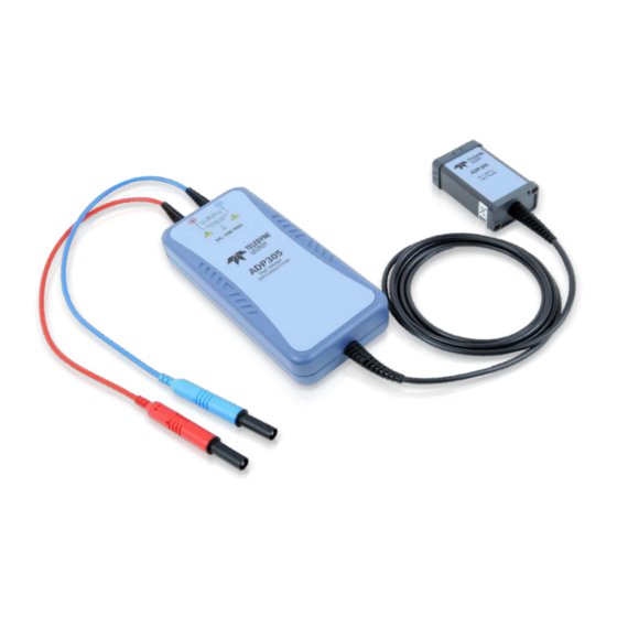
Active differential probe
Hide thumbs
1
2
3
Table Of Contents
4
5
6
7
8
9
10
11
12
13
14
15
16
17
18
19
20
21
22
23
24
25
26
27
28
29
30
31
32
33
34
35
36
37
38
page
of
38
Go
/
38
Contents
Table of Contents
Troubleshooting
Bookmarks
Table of Contents
Table of Contents
Safety Instructions
Introduction
Specifications
Standard Accessories
Operation
Connecting the Probe to the Test Instrument
Connecting the Probe to the Test Circuit
Operation with a Teledyne Lecroy Oscilloscope
Smart Offset
Bandwidth Limit (ADP305 Only)
Auto Zero
Remote Control Commands
Command List
Probe Auto Zero
Probe Bandwidth Limit
Probe Coupling
Probe Offset
Probe Volts/DIV
Maintenance
Calibration Interval
Service Strategy
Troubleshooting
Returning a Defective Probe
Replacement Parts
Functional Test
Performance Verification
Reference Information
Differential Mode and Common Mode
Differential Mode Range and Common Mode Range
Common Mode Rejection Ratio
Certifications
Contact Teledyne Lecroy
Advertisement
Quick Links
1
Performance Verification
Download this manual
Operator's
Manual
ADP300/305
Active Differential Probe
Table of
Contents
Previous
Page
Next
Page
1
2
3
4
5
Advertisement
Table of Contents
Need help?
Do you have a question about the ADP300 and is the answer not in the manual?
Ask a question
Questions and answers
Related Manuals for Teledyne Lecroy ADP300
Measuring Instruments Teledyne Lecroy AP033 Operator's Manual
Active differential probe (55 pages)
Measuring Instruments Teledyne Lecroy ADP305 Operator's Manual
Active differential probe (38 pages)
Measuring Instruments Teledyne Lecroy AP031 Operator's Manual
Differential probe (16 pages)
Measuring Instruments Teledyne Lecroy AP015 Operator's Manual
(26 pages)
Measuring Instruments Teledyne Lecroy Frontline 802.11 Hardware And Software Manual
802.11 a/b/g/n protocol analyzer (223 pages)
Measuring Instruments Teledyne Lecroy 980 User Manual
980 hdmi 2.1 protocol analyzer / generator (182 pages)
Measuring Instruments Teledyne Lecroy 280 Quick Start Manual
Test set video generator / analyzer (61 pages)
Measuring Instruments Teledyne Lecroy Mercury T2 User Manual
Usb protocol suite (515 pages)
Measuring Instruments Teledyne Lecroy Quantumdata 780E Quick Start Manual
Video generator / protocol analyzer for hdmi, displayport & hdbaset testing (12 pages)
Measuring Instruments Teledyne Lecroy HVD3000 Series Operator's Manual
High-voltage differential probes (44 pages)
Measuring Instruments Teledyne Lecroy WaveRunner 8000-R Getting Started Manual
Oscilloscopes (20 pages)
Measuring Instruments Teledyne Lecroy 980 User Manual
Sdi video generator/analyzer (322 pages)
Measuring Instruments Teledyne Lecroy PP021 Series User Manual
Passive probe (13 pages)
Measuring Instruments Teledyne Lecroy PCI Express 2.0 Mid-Bus Probe Installation And Usage Manual
For summit analyzers (29 pages)
Measuring Instruments Teledyne Lecroy HVD3102 Operator's Manual
High voltage differential probes (40 pages)
Measuring Instruments Teledyne Lecroy M42de Quick Start Manual
80 gbps video analyzer/generator (33 pages)
This manual is also suitable for:
Adp305
Table of Contents
Print
Rename the bookmark
Delete bookmark?
Delete from my manuals?
Login
Sign In
OR
Sign in with Facebook
Sign in with Google
Upload manual
Upload from disk
Upload from URL


Need help?
Do you have a question about the ADP300 and is the answer not in the manual?
Questions and answers