Table of Contents
Advertisement
Quick Links
Preliminary Information
Take care when handling this document.
Please do not show this document to any third party.
TOA RADIO MICROPHONE
CONTENTS
1. GENERAL DESCRIPTION
2. FEATURES
3. SPECIFICATIONS
4. TEST CONDITIONS
5. APPEARANCE
6. BLOCK DIAGRAM
7. CIRCUIT EXPLANATION
8. OPERATING INSTRUCTIONS
............................................................................ 2
......................................................................................................... 2
............................................................................................ 2
......................................................................................... 2
.................................................................................................. 5
........................................................................................... 6
............................................................................... 7
model WM-3310
....................................................................
WM-3310H
9
Advertisement
Table of Contents

Related Manuals for Toa WM-3310


Summary of Contents for Toa WM-3310
- Page 1 Preliminary Information Take care when handling this document. Please do not show this document to any third party. TOA RADIO MICROPHONE model WM-3310 WM-3310H CONTENTS 1. GENERAL DESCRIPTION ................2 2. FEATURES ......................2 3. SPECIFICATIONS .................... 2 4. TEST CONDITIONS ..................
- Page 2 1. GENERAL DESCRIPTION 1. GENERAL DESCRIPTION The TOA wireless microphone WM-3310 is of lavalier type and is designed to conform with the regulations. The TOA wireless microphone WM-3310 is of lavalier type and is designed to conform with the regulations.
- Page 3 [[Non-modulation] Disconnect the AF oscillator from the jig, then connect a 1 kΩ resistor (the same impedance as that of the microphone) to both the HOT and grounding terminals. (2) Connections for RF Measurement To measure an RF signal, use the coaxial cable attached to the microphone sample submitted. Connect the 3- pin connector from the coaxial cable to CN9 on the circuit board inside the microphone.
- Page 4 (6) Assembly/Disassembly of the Microphone <Disassembly> 1. Holding the upper cover, slide the battery case and push it up as shown in the figure. 2. Remove the battery. 3. Remove two screws using a Phllips screwdriver. (The upper cover can now be removed by hand.) 4.
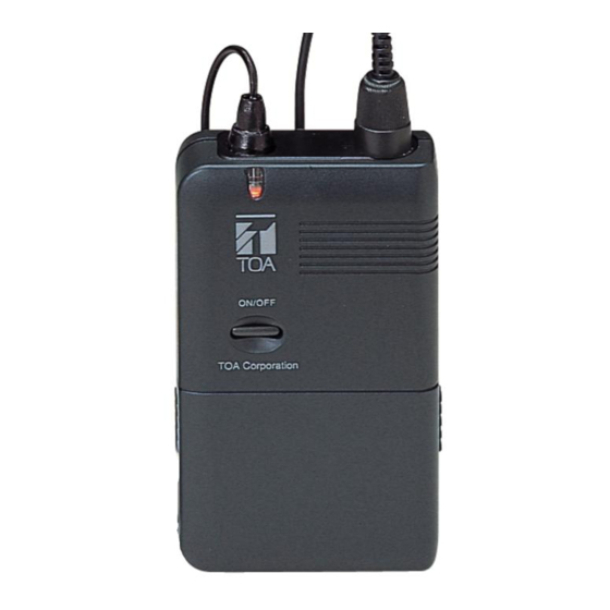
- Page 5 5. APPEARANCE [WM-3310] Power/Battery lamp Power/Battery lamp Power/Battery lamp Power/Battery lamp Power/Battery lamp Power/Battery lamp Power/Battery lamp Power/Battery lamp (Orange LED) (Orange LED) (Orange LED) (Orange LED) (Orange LED) (Orange LED) (Orange LED) (Orange LED) 23.5 23.5 23.5 23.5 23.5 23.5...
Need help?
Do you have a question about the WM-3310 and is the answer not in the manual?
Questions and answers