
Related Manuals for Renishaw SLM 250


Summary of Contents for Renishaw SLM 250
- Page 1 Installation and operation manual H-9942-9001-01-A SLM 250 scanning laser module For end users, installers, integrators and engineers...
- Page 2 Renishaw plc or responsibility of the user to ensure that, in the its subsidiaries. event of a failure on any part of the Renishaw system, the laser system remains safe. All other brand names and product names used...
- Page 3 The tests were carried out in compliance with: except for deviations pursuant to Laser Notice no. 50, dated June 24, 2007, the SLM 250 is Immunity to Table 2 – Industrial locations classified as a Class 1 invisible laser product.
- Page 4 Renishaw plc hereby declares that the SLM 250 This device may not cause harmful Contact Renishaw plc or visit is in compliance with the essential requirements interference, and www.renishaw.com/fanbeam for the full EC...
-
Page 5: Table Of Contents
SLM 250 . . . . . . . . . . . . . . . . . . . - Page 6 SLM 250 installation and operation manual Maintenance and care of the SLM 250 . . . . . . . . . . . . . . . . . . . . . . . . . . . . . . . . . . . . . . . 7-1 7 .1...
-
Page 7: General Safety
The product should only be connected to using the approved connector type and wiring as prescribed in section 4.2, “Cables”. • Changing the SLM 250 port and IP addresses must be carried out using only the SLM 250 software application by appropriately trained personnel. •... - Page 8 SLM 250 installation and operation manual This page is intentionally left blank.
-
Page 9: Customer Information
Customer information Dear Customer We congratulate you on the purchase of an SLM 250. You are now the owner of a high quality laser measurement device. However, we would ask you to take the time to work carefully through these operating instructions before using the instrument and to keep the manual with the instrument at all times. -
Page 10: Product Warranty
This warranty is given subject to the following conditions: • Renishaw plc shall be under no liability in respect of any defects in the equipment arising from any drawing, design or specification supplied or modification requested by the customer. -
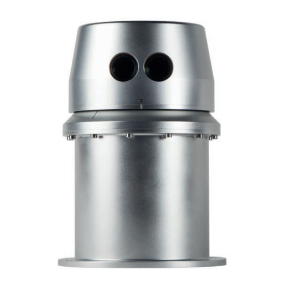
Page 11: Introduction
Introduction Figure 1: SLM 250 The SLM 250 is a ruggedised field instrument designed to produce fast, efficient 2D laser scans of the surrounding vicinity. It is designed to be used as a multi-purpose scanning distance meter that is integrated into other equipment for a variety of applications. -
Page 12: Applications
SLM 250 installation and operation manual Applications This unique instrument is suitable for a large number of surveying and measuring functions, such • security • quarrying and mining • coastal mapping • topographical surveys • highway infrastructure surveys • vehicle/vessel positioning. -
Page 13: Equipment Description
The flange at the bottom of the SLM 250 allows it to be mounted onto a stable surface (see section 15, “Appendix A – Mechanical drawings”). Its construction means it can be mounted vertically or... -
Page 14: Precautions
SLM 250 installation and operation manual Precautions • Avoid directing the laser apertures towards the sun or other high-powered, infrared light sources. • Avoid mechanical shock. The laser is driven by a motor. When the unit is stationary the laser can be rotated by hand without causing damage to the motor. -
Page 15: Low-Voltage Power Connectors
Appropriate visual inspection and electrical safety testing is to be performed after instrument installation or replacement. It is recommended that the SLM 250 is powered from an external 14 Vdc source with a minimum power capability of 100 W. Note: The SLM motor start-up peak current will be higher than its steady running current,... - Page 16 SLM 250 installation and operation manual This page is intentionally left blank.
-
Page 17: Laser Safety
In accordance with BS EN 60825-1 : 2007 and US standards 21CFR 1040.10 and 1040.11, except for deviations pursuant to Laser Notice no. 50, dated June 24, 2007, the SLM 250 is classified as a Class 1 invisible laser product. Safety eyewear is not required for the SLM 250. Do not stare into the beam or shine it into the eyes of others. - Page 18 Aligning the SLM 250 with the lenses of CCD-cameras or infrared night vision devices may result in damage to such devices and is therefore not permitted. The SLM 250 is intended for use in a locale where the emitted radiation is unlikely to be viewed with optical instruments.
-
Page 19: Operational Guidelines
The range information is transmitted via Ethernet using UDP messages. System limitations The SLM 250 is designed to meet IP66 and should not be used in situations that require a higher level of ingress protection. The SLM 250 is capable of measuring ranges up to 250 metres to 90% reflective material (e.g., Kodak white card). - Page 20 SLM 250 installation and operation manual This page is intentionally left blank.
-
Page 21: Maintenance And Care Of The Slm 250
Maintenance and care of the SLM 250 General Any attempt to dismantle or repair the SLM 250 by unauthorised personnel can be hazardous and costly. Maintenance carried out by the operator should be restricted to the cleaning and inspection of external surfaces, lenses and operating controls. -
Page 22: In Storage
7.2.3 In transportation The SLM 250 is supplied in dedicated packaging for delivery to the customer, and consideration should be given as to how to ship the unit once incorporated into a system. Do not allow the module to slide around inside transport vehicles or containers. -
Page 23: Network Set-Up
For first-time installation, communication needs to be correctly established between the PC/laptop and SLM 250. This requires the PC/laptop to have an IP address on the same subnet as the SLM 250. - Page 24 SLM 250 installation and operation manual Click the Networking tab. In the section This connection uses the following items, click Internet Protocol Version 4 (TCP/IPv4) and then click Properties (see Figure 4). Figure 4: Local area connection properties...
- Page 25 Enter the IP address of the PC/laptop in the section Use the following IP address. The IP address entered should be the same as that of the SLM 250 – except for the last three digits, which need to be a different number between 1 and 254. This must exclude the IP addresses currently in use for the SLM 250 unit and other equipment on that subnet.
- Page 26 SLM 250 installation and operation manual This page is intentionally left blank.
-
Page 27: Slm 250 Software
SLM 250 software Installing the SLM 250 software The SLM 250 software allows the user to set up and configure the module. It is loaded on the USB stick supplied with the instrument. This simple application enables the user to: •... - Page 28 SLM 250 installation and operation manual Choose a destination folder for the installation and click Install. The software will now be installed. Figure 7: Choose the install location To run the program, double-click the SLM250 icon. Figure 8: SLM250 icon For further information on how to use the software click Quick Start.
-
Page 29: Command List
ASCII line feed character. A UDP-enabled terminal program, such as the Hercules SETUP utility developed by the HW Group, can be used to communicate directly with the SLM 250 to help software development. - Page 30 SLM 250 installation and operation manual 10-2...
- Page 31 10-3...
- Page 32 SLM 250 installation and operation manual 10-4...
- Page 33 10-5...
- Page 34 SLM 250 installation and operation manual 10-6 This page is intentionally left blank.
-
Page 35: Rotation Speed And Resolution
Rotation speed and resolution The SLM 250 rotation speed can be varied from 1 Hz to 20 Hz, but the maximum firing frequency of the laser is 36 kHz and as such the resolution is altered by different rotation speeds. - Page 36 SLM 250 installation and operation manual 11-2 This page is intentionally left blank.
-
Page 37: Output Formats
Output formats Binary data format is recommended for normal operation of the SLM 250 as it is more efficient in passing large amounts of data. ASCII would most likely be used only for initial testing of the system as it can be easily displayed on terminal programs. - Page 38 SLM 250 installation and operation manual ASCII UDP stream format: $RRRRR,SSSS,GGGGG<cr><lf>$RRRRR,SSSS,GGGGG<cr><lf>… Where: Symbol Description Number of bits 12-2 Data header character (0x24) RRRRR Represents range SSSS Represents signal strength GGGGG Represents the angle in one-hundredths of a degree <lf> Line feed character (0x0A) <cr>...
-
Page 39: Binary Data Format
Binary data format The following command sequence outlines the start-up procedure after system power-up for configuring the SLM 250 to transmit binary format. Care should be taken when sending multiple H commands to ensure replies are toggled to the required state. - Page 40 SLM 250 installation and operation manual Scanning can be stopped with the command: Command Description SLM response (binary mode) ∗ Stop scan S TOPED Table 8: Binary command to stop scanning 12-4 The factory default number of frames (range, signal strength and angle data) contained in each...
-
Page 41: Beam And Tilt Angles
In practice, there are potential misalignments in both X and Y directions which are referred to as the “beam angle” and “tilt angle” respectively. These angles are measured and stored in the SLM 250 as part of the factory calibration process. They can be accessed using the commands in Table 9. - Page 42 SLM 250 installation and operation manual 13-2 This page is intentionally left blank.
-
Page 43: Specifications
Accuracy is defined as the degree of conformity of the measured sample mean range to its actual (real) value, measured with reference to a total station under Renishaw test conditions. Predicted accuracy and precision figures extrapolated from 10 m to 150 m. - Page 44 SLM 250 installation and operation manual Physical data Power 11 Vdc to 16 Vdc 80 W (running) Peak power up to 100 W Weight 4.8 kg Dimensions (L × W × H) 170 mm × 170 mm × 241.2 mm...
-
Page 45: Appendix A - Mechanical Drawings
Appendix A – Mechanical drawings 15-1... - Page 46 SLM 250 installation and operation manual 15-2 This page is intentionally left blank.
-
Page 47: Appendix B - Electrical Connections
Appendix B – Electrical connections 2000 mm 150 mm 2000 mm 2000 mm 16-1 1000 mm 150 mm 1000 mm 1000 mm E OF Wire Schedule DESCRIPTION TYPE Ground BLACK SINGLE (16AWG) FRONT FACE OF Positive CONNECTOR SINGLE (16AWG) Wire Schedule Schedule PAIR (CAT5E 26AWG) Figure 11: Umbilical cable connections... - Page 48 SLM 250 installation and operation manual 16-2 This page is intentionally left blank.
- Page 50 Renishaw plc +44 (0)1904 736736 +44 (0)1904 736701 Redwood House, Northminster spatialmeasurement@renishaw.com Business Park, York, North www.renishaw.com Yorkshire, YO26 6QR, UK For worldwide contact details, visit www.renishaw.com/contact *H-9942-9001-01*...
Need help?
Do you have a question about the SLM 250 and is the answer not in the manual?
Questions and answers