Table of Contents
Advertisement
Advertisement
Table of Contents

Related Manuals for Accumet AP75


Summary of Contents for Accumet AP75
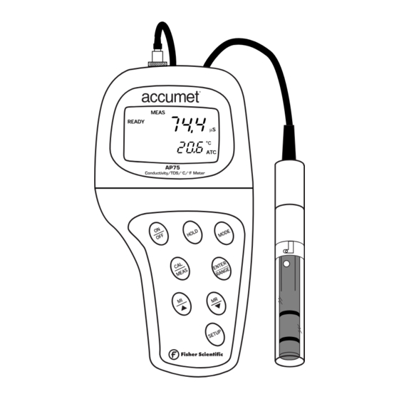
- Page 2 OPERATING INSTRUCTIONS accumet ® 13636AP75A Portable Waterproof Conductivity Meter MEAS READY µS Printed1/02...
-
Page 3: Table Of Contents
Table of Contents 1. Introduction....................4 2. Display and keypad functions .............5-6 2.1 Display ...........................5 2.2 Keypad ...........................6 3. Preparation ..................7-9 3.1 Inserting the batteries ......................7 3.2 Probe information ........................8 3.3 Connecting the probe to the meter ..................9 4. Calibration ..................10-16 4.1 Important information on meter calibration ..............10 4.2 Preparing the meter for calibration .................11 4.3 Conductivity calibration....................12-13... - Page 4 7.6 Program 5.0: Temperature ...................35-36 P5.1 Adjusting the temperature coefficient ..............35 P5.2 Adjusting the normalization temperature .............36 7.7 Program 6.0: Selecting the cell constant................37 7.8 Program 7.0: Setting the real-time clock..............38-39 7.9 Program 8.0: Resetting to factory defaults ..............40 8. Probe care and maintenance..............41 9.
-
Page 5: Introduction
1. Introduction Thank you for selecting an accumet AP75 waterproof portable meter. • Meter measures conductivity, TDS and temperature. • Microprocessor-based instrument is completely waterproof—and it floats! • Meter features a built-in real time clock, expanded memory, and many other user- friendly features, all of which are accessible through the membrane keypad. -
Page 6: Display And Keypad Functions
2. Display and Keypad Functions Display The LCD has a primary and secondary display. • The primary display shows the measured conductivity or TDS reading. • The secondary display shows the temperature of the reading. The display also shows error messages, keypad functions and program functions. Primary display Secondary display 15. -
Page 7: Keypad
Keypad The large membrane keypad makes the instrument easy to use. Each button, when pressed, has a corresponding graphic indicator on the LCD. ON/OFF ....Powers and shuts off the meter. HOLD ....Freezes the measured reading. To activate, press HOLD while in measurement mode. -
Page 8: Preparation
3. Preparation Inserting the Batteries Four AAA batteries are included with your meter. Use a Phillips screwdriver to remove the two screws holding the battery cover. See figure below. Lift off battery cover to expose batteries. Insert batteries. Follow the diagram inside the cover for correct polarity. Replace the battery cover into its original position. -
Page 9: Probe Information
Probe information Your accumet AP75 meter uses a conductivity/ TDS cell with a sturdy 6-pin connector. This cell is designed for use with accumet waterproof meters only. Your meter includes an Ultem/Stainless Steel cell with a cell constant of K = 1.0. This... -
Page 10: Connecting The Probe To The Meter
Connecting the probe to the meter Line up the notch and 6 pins on the meter with the holes in the 6-pin connector. Push down and turn the locking ring clockwise to lock into place. See figure below. To remove probe, turn the locking ring counterclockwise on the probe connector. Pull probe away from the meter. -
Page 11: Calibration
4. Calibration Important Information on Meter Calibration Your meter has five measuring ranges. You can calibrate at one point in each of the measuring ranges (up to five points). If you are measuring values in more than one range, make sure to calibrate each of the ranges you are measuring. To view current calibration points, see SETUP section Program 2.0 on page IMPORTANT: You need to calibrate your meter at a standard that is a minimum of 20% of the range in which you are measuring. -
Page 12: Preparing The Meter For Calibration
Preparing the Meter for Calibration Before starting calibration, make sure you are in the correct measurement mode. When you switch on the meter, the meter starts up in the units you shut it off in. For best results, select a standard value close to the sample value you are measuring. Alternatively use a calibration solution value that is approximately ⁄... -
Page 13: Conductivity Calibration
Conductivity calibration This meter is capable of up to 5-point conductivity calibration at one point per con- ductivity range (0.00-19.99 µS; 0.0-199.9 µS; 0-1999 µS; 0.00-19.99 mS; 0.0-199.9 mS). All new calibration data will over-ride existing stored calibration data for each measuring range you calibrate. -
Page 14: Conductivity Calibration
Notes When entering calibration mode, the meter will display the factory default value. If the meter was previously calibrated, the display may “jump” to the factory default value when switching from measurement to calibration mode. To exit from Conductivity Calibration mode without confirming calibration, DO NOT press ENTER in step 6. -
Page 15: Tds Calibration
TDS calibration 4.4.1 Calibrating for TDS directly: The factory default setting for TDS conversion factor is 0.5. If your solution has a different TDS factor, you can improve calibration accuracy by setting the TDS factor prior to calibration. See page 34 for directions. If necessary, press the MODE key to select TDS mode. -
Page 16: Calibration With Conductivity Standard And Tds Factor
4.4.2 Calibration with Conductivity standard and TDS factor The concentration of salts dissolved in solution increases the conductivity of that solution. This relationship varies from salt to salt and is roughly linear over a given range for a given salt. The TDS conversion factor is the number used by the meter to convert from conductivity to TDS. -
Page 17: Temperature Calibration
Temperature Calibration Your probe features a built-in temperature sensor. The temperature sensor is factory calibrated. Calibrate your sensor only if you suspect temperature errors that may have occurred over a long period of time or if you have a replacement probe. Temperature calibration Make sure the cell is attached to the 6-pin connector. -
Page 18: Measurement
5. Measurement This meter is capable of taking measurements with automatic or manual temperature compensation. Factory default is ATC on. Automatic Temperature Compensation For automatic temperature compensation (ATC) simply plug the conductivity/TDS probe into the meter (see page 9 for direc- tions). -
Page 19: Manual Temperature Compensation
Manual Temperature Compensation IMPORTANT: For manual compensation, you must deactivate the temperature probe. 5.2.1 Selecting Manual Temperature Compensation Select between Automatic Temperature Compensation (ATC) and Manual Temperature Compensation in the Set Up Program P4.3. Meter default is ATC on. From measurement mode Press Setup key to enter Set Up mode. -
Page 20: Manual Temperature Compensation
5.2.2 Setting a manual temperature compensation value To use manual temperature compensation, you need to enter the temperature value of your process into the meter. This is the value at which readings will manually temperature compensate. You can select any temperature between 0 and 100°C (32 and 212°F). -
Page 21: Taking Measurements
Taking Measurements To take readings: Rinse the probe with deionized or distilled water before use to remove any impurities adhering to the probe body. Shake or air dry. To avoid contamination or dilution of your sample, rinse probe with a small volume of your sample liquid. -
Page 22: Using Manual Ranging Function
Using Manual Ranging Function When shipped from the factory, your meter automatically selects the range in which your readings appear. The manual ranging function lets you select the specific range you want to work in: Conductivity 0.00-19.99 µS; 0.00-9.99 ppm; 0.0-199.9 µS;... -
Page 23: Hold Function
Hold Function This feature lets you freeze the display for a delayed observation. HOLD can be used any time when in MEAS mode. To hold a measurement, press the HOLD key while in measurement mode. "HOLD" will appear on the display. -
Page 24: Memory And Data Input Functions
6. Memory and data input functions Memory Input Your meter stores up to 50 sets of data. Data sets include conductivity, temperature, date, and time. To store a reading: During any measurement function (MEAS), press the MI key to input any data into the memory MEM, “Sto”... -
Page 25: Memory Recall
Memory Recall This function recalls the previous readings stored in the memory. You can only access MR from the MEASurement mode. Memory recall is in “Last In First Out” order. To recall readings: Press the MR key once to retrieve the last reading stored. -
Page 26: Setup Functions
7. Advanced set up mode The advanced set up mode lets you customize your meter’s preferences and defaults. Your waterproof meter features different sub groups that organize all set-up parameters. The sub groups are: P1.0: Memory clear (CLR) P2.0: Viewing calibration data (CAL) P3.0: Viewing probe data (ELE) P4.0: Unit configuration (COF) P5.0: Temperature (tPr) -
Page 27: Set Up Mode Overview
Set-up mode overview SETUP Press the key to enter Set up mode. Press the keys to scroll between sub groups. ENTER Press the key to enter a particular parameter. See Addendum 5 on page 49 for a table of meter factory default settings. P1.0: Memory clear •... - Page 28 P5.0: Temperature • P5.1: Adjusting temperature coefficient • P5.2: Adjusting normalization temperature Instructions on page 35-36 P6.0: Selecting cell constant • P6.1: Selecting cell constant: K = 1.0, 10, or 0.1 Instructions on page 37 P7.0: Setting clock • Setting year •...
-
Page 29: Program 1.0: Memory Clear
P1.0: Memory Clear Use this parameter to clear all memory values when you need to store a new series of values. This lets you avoid confusing the old values with the new ones. NO is the default setting. NOTE: Selecting YES will wipe out all memory. From measurement mode: Press the Set up key to enter Set Up mode. -
Page 30: Program 2.0: Viewing Calibration Data
P2.0: Viewing calibration data This mode lets you recall previous calibration data, which helps you know when to recalibrate your meter. This is a “view only” mode. From measurement mode: Press the Set up key to enter Set Up mode. See figure Press the keys to scroll through... -
Page 31: Program 3.0: Viewing Probe Data
P3.0: Viewing probe data Program 3 has five "view only" options that let you check your probe’s parameters for diagnostic purposes. These options show you the effective cell constant for each range. The cell constant is adjusted according to your calibration. From measurement mode: Press the Set up key to enter Set Up mode. -
Page 32: Program 4.0: Unit Configuration
P4.0: Unit configuration P4.1: READY indicator and auto endpoint function Program P4.1 lets you select “READY indicator on” to indicate when your measure- ment is stable, or select “READY indicator off” for faster meter response. Program P4.1 also lets you switch the Auto endpoint function on or off. Select auto endpoint on to “hold”... -
Page 33: P4.2 Selecting °C Or °F
P4.2 Selecting °C or °F You can select between °C and °F units for temperature readings. Meter default is °C. From measurement mode Press Setup key to enter Set Up mode. Press the keys to scroll through subgroups until you view parameter P4.0. See figure Press the ENTER key two times to select parameter 4.2. -
Page 34: P4.3 Selecting Automatic Or Manual Temperature Compensation
P4.3 Selecting Automatic or Manual Temperature Compensation This feature lets you select between Automatic Temperature Compensation (ATC) and Manual Temperature Compensation. Meter default is ATC. From measurement mode Press Setup key to enter Set Up mode. Press the keys to scroll through subgroups until you view parameter P4.0. -
Page 35: P4.4 Setting The Tds Factor
P4.4 Setting the TDS factor The concentration of salts dissolved in solution increases the conductivity of that solution. This relationship varies from salt to salt and is roughly linear over a given range for a given salt. The TDS conversion factor is the number used by the meter to convert from conductivity to TDS. -
Page 36: Program 5.0: Temperature
P5.0: Temperature P5.1 Adjusting the temperature coefficient The temperature coefficient is the amount of change in conductivity per degree of temperature; it is expressed in percent per °C or °F. Entering the exact temperature coefficient of your solution lets you accurately compensate temperature for almost any solution*. -
Page 37: P5.2 Adjusting The Normalization Temperature
P5.2 Adjusting the normalization temperature Your meter will normalize its conductivity measurements to a standard temperature that you can select. You can adjust the normalization temperature from 15 to 30°C (59 to 86°F). Meter default is 25°C (77°F). From measurement mode Press Setup key to enter Set Up mode. -
Page 38: Program 6.0: Selecting The Cell Constant
P6.0: Selecting the cell constant Your meter lets you select a cell constant of K = 1.0, 10, or 0.1. • Use a cell of K = 1.0 for midrange measurements • Use a cell of K = 10 for high range measurements (above 20 mS or 10 ppt) •... -
Page 39: Program 7.0: Setting The Real-Time Clock
P7.0: Setting the clock Your meter features a real-time calendar and clock. This helps you meet GLP (Good Laboratory Practice) standards. From measurement mode Press Setup key to enter Set Up mode. keys to scroll through Press the subgroups until you view parameter P7.0. - Page 40 Press the ENTER key to confirm the date and move to “hour” selection. The “hour” digits will flash. See figure Press the keys to toggle to the correct hour. Note the “AM” and “PM” indicator on the lower portion of the display. Press the ENTER key to confirm the hour and move to “minute”...
-
Page 41: Program 8.0: Resetting To Factory Defaults
P8.0: Resetting to factory default settings Program 8.0 lets you reset all parameters to factory default settings. This clears all calibration data, memory, and any other setup functions you might have changed. It does not clear clock settings. From measurement mode Press Setup key to enter Set Up mode. -
Page 42: Probe Care And Maintenance
8. Probe Care and Maintenance Keep the conductivity probe clean. Rinse the probe twice, and gently swirl it while you take readings. For best accuracy, soak a dry probe for at least 5 to 10 minutes or longer before calibration. Rinse the probe with deionized or tap water before storing. Never scratch the platinum portions with a hard substance. -
Page 43: Troubleshooting
9. Troubleshooting Cause Solution Problem Power on but a) Batteries not in place. a) Check that batteries are in no display place and making good contact. b) Batteries not in correct b) Reinsert batteries with polarity (+ and –). correct polarity. c) Weak batteries. -
Page 44: Error Messages
10. Error Messages Indicates Cause Solution Display Unrecognized input Wrong input in Release key. Select annunciator from keypad selected mode. valid operations depending on mode. CAL & Err Calibration error Wrong buffer value Check your calibration annunciators on/ input at calibration. input value, clean probe. -
Page 45: Specifications
11. Specifications Mode Conductivity Temperature Range 0.00 to 19.99 µS (0.01 µS) 0.00 to 9.99 ppm (0.01 ppm) 0.0 to 100.0°C (Resolution) 0.0 to 199.9 µS (0.1 µS) 10.0 to 99.9 ppm (0.1 ppm) 0 to 1999 µS (1 µS) 100 to 999 ppm (1 ppm) 32.0 to 212.0°F 0.00 to 19.99 mS (0.01 mS) 1.00 to 9.99 ppt (0.01 ppt) -
Page 46: Addendum 1: Calibration Tips
12. Addendum 1: Calibration Tips You only need one calibration for measurement throughout the entire range of the meter. If a range was not calibrated, the meter automatically detects the closest range calibrated and uses that calibration information. However, only the ranges that were calibrated have maximum accuracy. -
Page 48: 14: Addendum 3: Calculating Tds Conversion Factors
14. Addendum 3: Calculating TDS Conversion Factors You can calibrate your meter using TDS calibration standard solutions. The calibra- tion standard only needs to give the TDS value at a standard temperature such as 25°C. To determine to the conductivity-to-TDS conversion factor use the following formula: Factor = Actual TDS ÷... -
Page 49: Addendum 4: Calculating Temperature Coefficients
15. Addendum 4: Calculating Temperature Coefficients To determine the temperature coefficient of your sample solution use this formula: TC = 100 x _________________________ - 25) - C - 25) TC = Temperature coefficient =Conductivity at Temp. 1 = Conductivity at Temp. 2 = Temp. -
Page 50: Addendum 5: Meter Factory Default Settings
16. Addendum 5: Meter factory default settings Type Parameter Default Remarks P1.0 Memory clear Retains current memory P2.1 Viewing previous – – – No calibration data for 1st range calibration data P2.2 – – – No calibration data for 2nd range P2.3 –...
Need help?
Do you have a question about the AP75 and is the answer not in the manual?
Questions and answers