Table of Contents
Advertisement
Quick Links
Advertisement
Table of Contents

Related Manuals for Infinite Play Pleats


Summary of Contents for Infinite Play Pleats
- Page 1 Installer manual Z4010...
-
Page 2: Table Of Contents
Pleats CONTENTS PLEATS VIDEO DOOR ENTRY SYSTEM ITEM Z4010 ..................................3 1-General information ........................................... 3 1.1-Product description .......................................... 3 1.2-Front view ............................................4 1.3-Rear view ............................................4 1.4-Side and bottom view ........................................4 1.5-Description of buttons ........................................5 2-Installation of video door entry system ...................................... 7 2.1-Types of installation .......................................... -
Page 3: Pleats Video Door Entry System Item Z4010
1-General information 1.1-Product description The product PLEATS item Z4010, is a hands-free IP video door entry system with POE power supply. It is provided with a 4.3” LCD display. The video door entry system is equipped with a proximity sensor that turns the device on when the user gets near to it. -
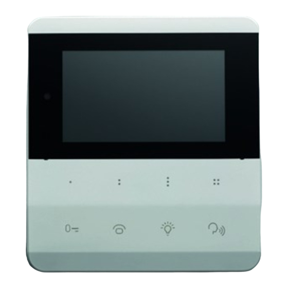
Page 4: Front View
Pleats 1.2-Front view Colour LCD display Microphones Proximity sensor Programmable touch buttons 1.3-Rear view Auxiliary Connectors Ethernet connector Speaker... -
Page 5: Side And Bottom View
Pleats 1.4-Side and bottom view Reset button Mini USB connector Volume buttons... -
Page 6: Description Of Buttons
Pleats 1.5-Description of buttons... - Page 7 Pleats BUTTON PRIMARY FUNCTION SYMBOL Programmable button 1 (In the menus it is used as BACK button) Programmable button 2 Programmable button 3 (In the menus it is used as SELECT button) Programmable button 4 (It is used as SOS button if set by the operator) Programmable button 5 (Generally used for video door entry system function "gate electric lock opening")
-
Page 8: 2-Installation Of Video Door Entry System
2-Installation of video door entry system 2.1-Types of installation The PLEATS video door entry system can be installed in the following configurations: 1-Unified rectangular wall-mounted box with 3 modules in horizontal configuration, mounting plate and two M3 screws. 2-Unified rectangular wall-mounted box with 3 modules in vertical configuration, mounting plate, one M3 screw, two self-tapping screws and two wall plugs. -
Page 9: How To Install The Video Door Entry System
3-Insert the video door entry system on the hooks of the mounting plate. 4-Slide the video door entry system down to lock it on the mounting plate. Installation Mounting plate Hooks for PLEATS installation Cable hole Height from the ground 145-150cm To remove the video door entry system it is necessary to slide it upwards and then remove it from the support. -
Page 10: 3-Terminals And Connectors Of The Video Door Entry System
Pleats 3-Terminals and connectors of the video door entry system The following terminals and connectors are located on the back of the PLEATS video door entry system. Figure 2 Ethernet connector 8-pole clamp -8-pole clamp: Used for additional 24V power supply (in case the POE power supply is not available). -
Page 11: How To Wire An Ethernet Cable
Pleats 5-Specifications for wiring The interconnecting cables used must be UL certified and must meet the requirements of the CEI 64/8 standard for video door entry systems: -UTP CAT 5e for internal sections dedicated to video door entry systems only... -
Page 12: Settings
It is possible to set a "friendly name" to the device, which will identify it in the Infiniteplay system. 3-Language It is possible to select from a list the language to be applied to the PLEATS video door entry system. 4- Time zone It is possible to select the desired time zone from a list. -
Page 13: 10-Doctor Mode
Note: To apply the changes select "Save configuration" at the end of the list. 13.1.1-Visibility It is possible to select the devices to make visible to the PLEATS video door entry system. Then tick the desired devices and press "done". -
Page 14: 5-Intercom Groups
Pressing "Power Supplies" will display the power supplies that can be configured. Select a power supply and associate the desired function to the outputs. To use the functions it is necessary to map them on the PLEATS buttons (13.1.2-Buttons mapping). 13.2.6-Entrance panels mapping Through the entrance panels mapping, it is possible to set the devices that can be called from the entrance panels. -
Page 15: Connection Diagrams
Pleats CONNECTION DIAGRAMS 1-Single-family video door entry system Composed of an external entrance panel, a power supply and an internal video door entry system. HOME INTERNET Video door phone Relay additional chime Relay additional chime Alarm INPUT Outdoor call button... -
Page 16: 2-Two-Family Video Door Entry System
Pleats 2-Two-family video door entry system Composed of an external entrance panel, a power supply and two internal video door entry systems Relay additional chime Relay additional chime Alarm INPUT Outdoor call button Panic Button Power - Power +12V Video door phone 2... -
Page 17: 3-Two-Family Video Door Entry System With Firewall
Pleats 3-Two-family video door entry system with firewall Composed of an external plate, a power supply, a firewall and two internal video door entry systems. The system is equipped with internet access. HOME INTERNET CAT5 Video door phone 2 with internet connection... -
Page 18: 4-Multi-Family Video Door Entry System
Pleats 4-Multi-family video door entry system Composed of an external entrance panel, a power supply, distributors and multiple video door entry systems. Video door phone Video door phone CAT5 WIRING SPECIFICATIONS CLAMP CABLE MAX. CONNECTOR LENGTH P1-P2-P3- Eth CAT5 100 metres... -
Page 19: 5-Building Complex
Pleats 5-Building complex Composed of two entrance panels, a power supply, a video door entry system, two distributors and a concierge switchboard. Video door phone Video door phone CAT5 Entrance panel 12Vcc 1A Lock INTERNET of building CONCIERGE CAT5 12Vcc 1A Lock... -
Page 20: 6-Additional Ringtone And Optional Buttons Connection Diagram
Pleats 6-Additional ringtone and optional buttons connection diagram Additional chime C.A. Power supply 12 Vdc Power supply Relay additional chime 230Vac Relay Relay additional chime Alarm INPUT Outdoor call button Panic Button Power - Power +12V RJ45 Video door phone Additional chime C.C. -
Page 21: 7-Staircase Lighting Control Connection Diagram
Pleats 7-Staircase lighting control connection diagram Lock return 12Vcc 1A Lock PORTE RJ45 Mains 90-260Vac Power Supply 50-60Hz Z6001 GND GND AUX1 AUX2 AUX3 AUX1- Stair light STAIRS LIGHT CONTOL 2A@24Vdc 8-Door opening command connection diagram wire 1,5mm2 PORTE RJ45... - Page 22 Pleats Installer notes...
- Page 23 Pleats Installer notes...
- Page 24 Pleats Directive 2012/19/EU (WEEE, RAEE). The crossed-out bin symbol indicates that the product must be delivered to a separate collection center for electrical and electronic equipment, or returned to the retailer when a new product is purchased. For information regarding the collection systems available, contact your local waste disposal service.
- Page 25 InfinitePlay S.r.l. Via Antonio Ferrero, 9 - 35133 Padova (PD) ITALY Tel. 049 706344 www.infiniteplay.com – 18901080 RL05 03 18 INFINITEPLAY - ITALY...
Need help?
Do you have a question about the Pleats and is the answer not in the manual?
Questions and answers