Table of Contents
Advertisement
Quick Links
IMPORTANT: THIS DEVICE MUST BE PROFESSIONALLY INSTALLED.
READ AND UNDERSTAND ALL INSTRUCTIONS BEFORE BEGINNING INSTALLATION.
The Miller Edge RBand Monitored Gate Edge Transmitter/Receiver system is intended to provide a wireless
connection between a monitored sensing edge and a motorized operator that controls the associated gate. RBand
meets the 2016 UL 325 requirements for monitored devices and has been certified as a UL 325 Recognized
Component. It is designed for use with operators that comply with 2016 UL 325 using a Miller Edge 10K Sensing
Edge.
1. PARTS LIST
Kit Contents:
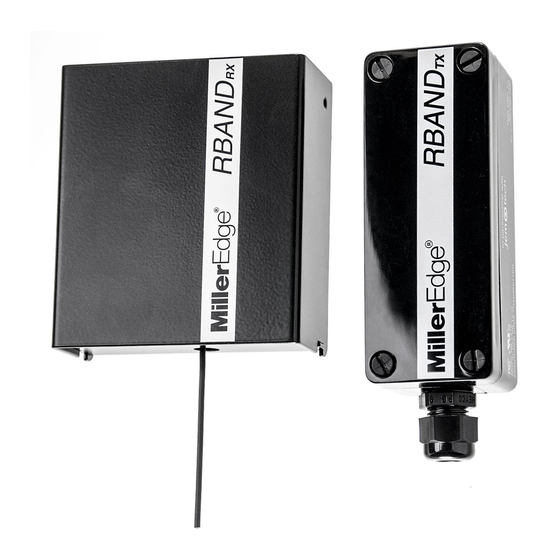
1. RBand Edge Transmitter (RB-TX10)
2. RBand Gate Edge Receiver (RB-G-RX10)
3. Receiver antenna
4. (2) 3.6V AA lithium batteries*
5. (4) #6 pan head transmitter mounting screws
*Replacement 3.6V AA lithium batteries can be
purchased at your local electronics store or via
Miller Edge.
2. RECEIVER: INSTALLATION
2-1. Remove operator cover and turn off the power to the gate operator.
2-2. Determine where to place the external mounted antenna so it is in line of sight with the Transmitter for the
entire range of travel [IMAGE 1]. Prepare the antenna coax as necessary.
2-3. Remove Receiver cover and mount the base inside the operator, positioning it for optimum ease of wiring.
2-4. Connect power to the terminals marked 12/24 AC/DC (polarity sensitive) on the removable 8-pin
connector [IMAGE 2].
2-5. Determine which monitored interface your operator uses. Connect the COM (C1/C2) and the correct output
connections (N.C. = CS1/CS2 or 10K = BS1/BS2) to your operator. There are 2 separate relays (channels):
R1 and R2. The A Test terminals must be used for operators requiring N.C. inputs. Enable with DIP switch 4
[TABLE 1].
2-6. Replace the Receiver cover and turn on power to the operator. Note: it takes ~5 seconds for the Receiver to
initialize.
Note: RBand 10K Gate Edge Receiver is compatible with up to 3 RBand Transmitters on 2 channels (6 total).
WIRING
ANTENNA
RBAND RECEIVER
MOUNTED INSIDE OPERATOR
WITH EXTERNAL ANTENNA
www.milleredge.com
OPERATOR
IMAGE 1. RBand Transmitter Installation with Gate Edge
info@milleredge.com
INSTALLATION INSTRUCTIONS
Required:
•
1/8" flat blade screwdriver
•
1/4" flat blade screwdriver
•
Miller Edge 10K (T2/blue band) Sensing Edge
•
Coaxial cable for exterior mounted antenna
•
Coaxial bulkhead adapter, female/female
Recommended:
•
Multi-meter capable of reading 10KΩ
•
Mounting screws for the Receiver
SENSING EDGE
Model: RB-G-K10
RBAND TRANSMITTER
MOUNTED NEAR
SENSING EDGE
RB-G-K10_Install_A4_20170706
800-220-3343
Advertisement
Table of Contents

Related Manuals for Miller Edge RBAND


Summary of Contents for Miller Edge RBAND
-
Page 1: Installation Instructions
RBand meets the 2016 UL 325 requirements for monitored devices and has been certified as a UL 325 Recognized Component. It is designed for use with operators that comply with 2016 UL 325 using a Miller Edge 10K Sensing Edge. -
Page 2: Led Indicators
Relay Output 3 „ Low battery alarm (optional) „ Low battery alarm (optional) N.C. Power Cycling COM. „ COM: Switched power Common A TEST „ +12/24VDC: Switched power IMAGE 2. RBAND GATE EDGE RECEIVER PCB & CONNECTIONS source www.milleredge.com info@milleredge.com 800-220-3343... -
Page 3: Troubleshooting
MOUNTING HOLES ALIGNMENT PIN STRAIN RELIEF FITTING IMAGE 3. RBand Edge Transmitter PCB & Connections 3. TRANSMITTER: PROGRAM MODE 3-1. Confirm the Receiver is powered up. Prior to mounting the Transmitter, remove the cover and insert the batteries, noting their polarity. The green LED on the Transmitter should blink to indicate that it has not been associated with the Receiver yet [IMAGE 3]. -
Page 4: Fcc Compliance
TX Indicator Lights: • Green LED: Normally off • Press program button for status 9. FCC COMPLIANCE RBand Transmitter RBand Receiver Model: RB-TX10 Model: RB-G-RX10 FCC ID: U5Z-RB-TX10 FCC ID: U5Z-RB-G-RX10 This device complies with Part 15 of the FCC rules. Operation is This device complies with Part 15 of the FCC rules. - Page 5 NORMALLY CLOSED ADDENDUM: Removable Connector Assignments by Manufacturer All-O-Matic CS1 C1 BS1 CS2 C2 BS2 NO3 C3 1 2 3 4 12/24 AC/DC COM.A TEST DIP Switch #4 • Turn to on HySecurity CS1 C1 BS1 CS2 C2 BS2 NO3 C3 1 2 3 4 12/24 AC/DC COM.A TEST...
Need help?
Do you have a question about the RBAND and is the answer not in the manual?
Questions and answers