Advertisement
READ AND UNDERSTAND ALL INSTRUCTIONS BEFORE BEGINNING INSTALLATION.
Parts List
1-
PART NUMBER
MWR12 Single Channel Receiver
MWT12 Single Channel Transmitter
MWTA12 Single Channel Transmitter with low
Kits:
battery alarm
MWRT12: includes MWR12, MWT12
Install Transmitter and Test
MWRTA12: includes MWR12 and MWTA12
2-
2-1. Open and unpack the batteries, Transmitter
and Receiver units.
2-2. Loosen Top Lid Screws on the Transmitter and remove lid.
Remove the Receiver Top Lid by pressing one side of the
snap lock base inward while lifting lid.
2-3. Set the 9 Pole, 3 Position Coding Switch on the Receiver to
match the Transmitter's 9 Pole, 3 Position Coding Switch. Any
switch position will work as long as the Transmitter coding switch
and the Receiver coding switch are exactly matched (must be
different from other nearby transmitters of the same type).
2-4. Place the two (2) AA batteries in their holders on the Transmitter
Momentarily press the Test Button on the Transmitter.
in the proper direction, paying attention to the (+) and (-) ends.
The Green Tx LED Indicator should light for 3 seconds.
To test the Alarm on the MWTA12 Model, press and hold the
Test Button. The Alarm should sound in approximately ten (10)
seconds. Release the Test Button.
the Transmitter's Strain Relief Cable Fitting for
2-5. Route the wires from the safety edge through
approximately four inches.
Terminal Block off the Transmitter's PCB. Place the safety
2-6. Strip the insulation from the two wires back ¼". Pull the
edge wires in the Terminal Block and tighten with screwdriver.
Re-seat the Terminal Block on the PCB (see Fig. 2-6).
tighten the Strain Relief Cable Fitting.
2-7. Re-seat the PCB into the Transmitter Enclosure and securely
2-8. Now, compress your safety edge. The Green Tx LED Indicator
should light for about 3 seconds.
P.O. Box 159 • West Grove, PA 19390 • 800-220-3343 • 610-869-4422 • Fax: 610-869-4423 • www.milleredge.com
6809 South Harl Ave., Suite A • Tempe, AZ 85283 • 800-887-3343 • 480-755-3565 • Fax: 480-755-3558
Model # MWTA12, MWT12, MWR12, MWRT12, MWRTA12
IMPORTANT:
Tools Required:
1. 1/8" Flat blade screwdriver for wire connections
2. 1/4" Flat blade screwdriver for top lid screws
Recommended:
DVM for test purposes
(4) #6 - 20 x 3/4" self-drilling screws included,
Sensing edge (sold separately)
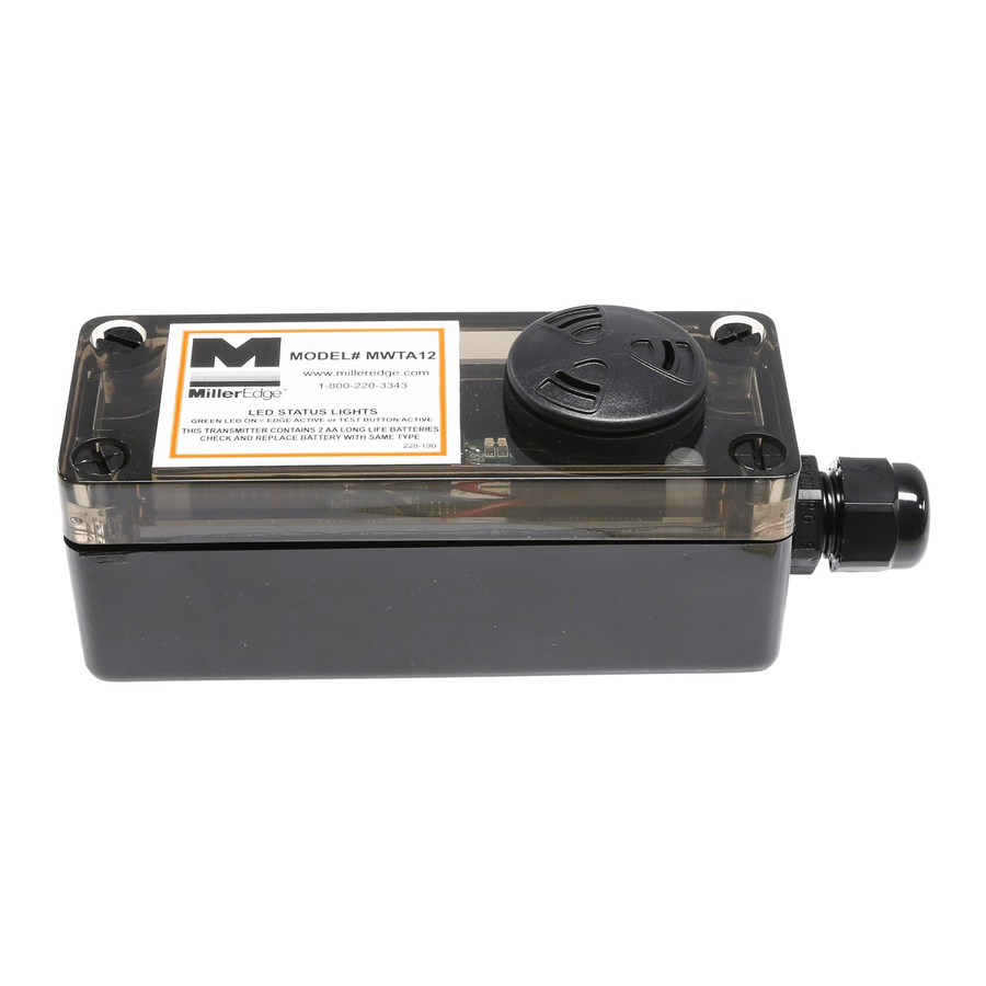
TRANSMITTER ENCLOSURE
Shown with Optional Alarm
TOP LID
SCREWS
9 POLE,
3 POSITION
CODING SWITCH
AA LITHIUM
BATTERIES
STRAIN RELIEF
CABLE FITTING
(-)
Fig. 2-6 WIRE CONNECTION TO
(+)
TERMINAL BLOCK
TEST BUTTON
GREEN TX
LED INDICATOR
(+)
TERMINAL
BLOCK
Safety Edge
Connection
(-)
MWTA12_Inst_20131007
Advertisement
Table of Contents

Related Manuals for Miller Edge MWTA12


Summary of Contents for Miller Edge MWTA12
-
Page 1: Parts List
GREEN TX AA LITHIUM LED INDICATOR BATTERIES To test the Alarm on the MWTA12 Model, press and hold the Test Button. The Alarm should sound in approximately ten (10) seconds. Release the Test Button. the Transmitter’s Strain Relief Cable Fitting for 2-5. - Page 2 Install Transmitter and Test Cont. (4) PRE-DRILLED 2-9. The four (4) Pre-Drilled Corner Mounting Holes CORNER MOUNTING HOLES are located on the far corners of the Transmitter Enclosure. Mount the Transmitter to the gate post, door end stile, or bottom angle using (4) #6 - 20 x 3/4”...
-
Page 3: Fcc Compliance
Cable Connections: Screw clamp type terminal blocks for 14-26 awg wire. Dimensions: MWT12: 5.75”w x 1.75”h x 1.8”d Antenna: Integral helical antenna. MWTA12: 5.752”w x 2.125”h x 1.8”d Test Button: Momentary push button – Forces the transmission of the transmitter's address. Low Battery: Transmitted Signal Duration: Approx. 3 seconds Model #MWTA12 only: 80-95dB Audible Alarm Response Time: Nominal 70 msec;...
Need help?
Do you have a question about the MWTA12 and is the answer not in the manual?
Questions and answers