Advertisement
Quick Links
READ AND UNDERSTAND ALL INSTRUCTIONS BEFORE BEGINNING INSTALLATION.
Parts List
1-
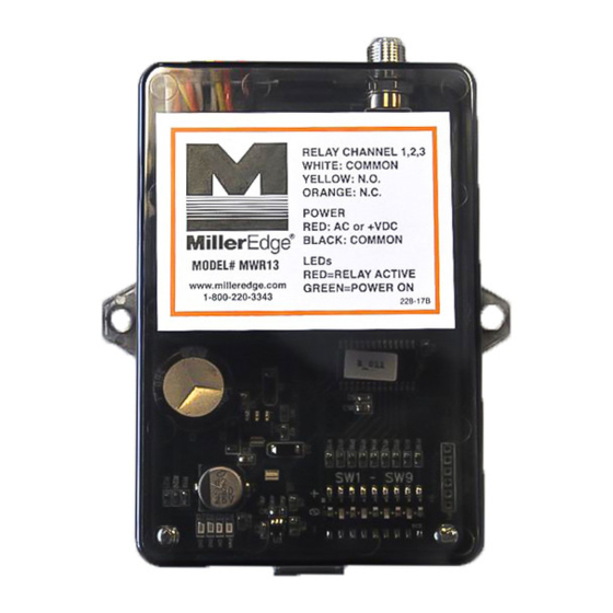
PART NUMBER
MWR13 Three Channel Receiver
MWT12 Single Channel Transmitter
MWTA12 Transmitter with low battery alarm
Install Transmitter and Test
2-
2-1. Open and unpack the batteries, Transmitter
and Receiver units.
2-2. Loosen Top Lid Screws on the Transmitter and remove lid.
Remove the Receiver Top Lid by pressing one side of the
snap lock base inward while lifting lid.
2-3. Setting the DIP switches. Switch positions, 1 through 8 in your
transmitter(s) must be set identically. Switch #9 in the transmitter
will determine which channel's relay in the receiver will
be activated. In the transmitter that you wish to activate receiver
Channel 1, set #9 to "+", for the Channel 2 transmitter, set #9 to
"0", a Channel 3 transmitter would have #9 set to "-".
2-4. Place the two (2) AA batteries in their holders on the Transmitter
in the proper direction, paying attention to the (+) and (-) ends.
Green Tx LED Indicator should light for 3 seconds.
Momentarily press the Test Button on the Transmitter. The
To test the Alarm on the MWTA12 Model, press and hold down
the Test Button. The Alarm should sound in approximately ten
(10) seconds. Release Test Button.
the Transmitter's Strain Relief Cable Fitting for
2-5. Route the wires from the safety edge through
approximately four inches.
Terminal Block off the Transmitter's PCB. Place the safety
2-6. Strip the insulation from the two wires back ¼". Pull the
edge wires in the Terminal Block and tighten with screwdriver.
Re-seat the Terminal Block on the PCB (see Fig. 2-6).
tighten the Strain Relief Cable Fitting.
2-7. Re-seat the PCB into the Transmitter Enclosure and securely
2-8. Now, compress your safety edge. The Green Tx LED Indicator
should light for about 3 seconds.
IMPORTANT:
Tools Required:
1. 1/8" Flat blade screwdriver for wire connections
2. 1/4" Flat blade screwdriver for top lid screws
Recommended:
www.GateOpenerSafety.com
Model # MWR13, MWT12, MWTA12
DVM for test purposes
(4) #6 - 20 x 3/4" self-drilling screws, as required
Sensing edge (sold separately)
TRANSMITTER ENCLOSURE
Shown with Optional Alarm
TOP LID
SCREWS
9 POLE,
3 POSITION
CODING SWITCH
AA LITHIUM
BATTERIES
STRAIN RELIEF
CABLE FITTING
(-)
Fig. 2-6 WIRE CONNECTION TO
(+)
TERMINAL BLOCK
TEST BUTTON
GREEN TX
LED INDICATOR
(+)
TERMINAL
BLOCK
(Safety Edge
Connection)
(-)
MWRT13_Inst_20131007
Advertisement

Related Manuals for Miller Edge MWR13


Summary of Contents for Miller Edge MWR13
- Page 1 Model # MWR13, MWT12, MWTA12 IMPORTANT: READ AND UNDERSTAND ALL INSTRUCTIONS BEFORE BEGINNING INSTALLATION. Parts List PART NUMBER Tools Required: 1. 1/8” Flat blade screwdriver for wire connections MWR13 Three Channel Receiver 2. 1/4” Flat blade screwdriver for top lid screws...
- Page 2 Install Transmitter and Test Cont. (4) PRE-DRILLED 2-9. The four (4) Pre-Drilled Corner Mounting Holes CORNER MOUNTING HOLES are located on the far corners of the Transmitter Enclosure. Mount the Transmitter to the gate post, door end stile, or bottom angle using (4) #6 - 20 x 3/4”...
- Page 3 Specifications and Controls: Transmitter Unit Code Switch: Selectable 9 pole, 3 position DIP Frequency: 318 MHz. Indicator Lights- Tx: Green LED: Tx Data Mounting: (4) #6 self drilling screws included Power Source: Batteries: 2 AA, 1.5v Alkaline or Lithium* Enclosure Rating: NEMA4 *Recommended for extended life in prolonged cold environments.
Need help?
Do you have a question about the MWR13 and is the answer not in the manual?
Questions and answers