
Related Manuals for Aqualisa QUARTZ DIGITAL SERIES


Summary of Contents for Aqualisa QUARTZ DIGITAL SERIES
- Page 1 Quartz Digital Bath with overflow filler Installation guide Quartz bath with overflow filler installation instructions Page 1...
- Page 2 Quartz Digital Bath with overflow filler Quartz Digital Bath with bath overflow filler Quartz bath with overflow filler installation instructions Page 2...
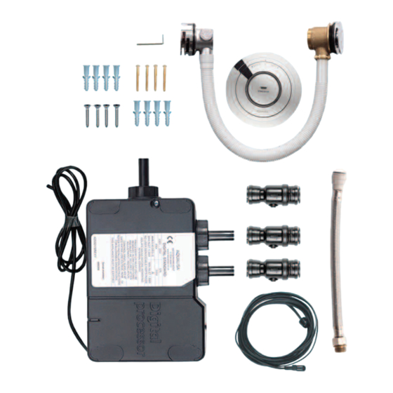
- Page 3 Components (HP/Combi) Literature not shown. Components (Gravity pumped) Literature not shown. Quartz bath with overflow filler installation instructions Page 3...
-
Page 4: Safety Information
Important information Safety information This product must be installed by a competent person in accordance with all relevant current Water Supply Regulations. ALL SHOWERS REQUIRING AN ELECTRICAL CONNECTION MUST BE INSTALLED BY A QUALIFIED PERSON FOLLOWING THE LATEST REVISION OF BS 7671 (WIRING REGULATIONS) AND CERTIFIED TO CURRENT BUILDING REGULATIONS. - Page 5 Cables which are chased into the wall must be protected by a suitably sized conduit or sheathing to allow for removal in the event of service and maintenance purposes. Surface mounted cables must also be protected by a suitable approved conduit, even in a loft, where there may be a risk of damage from vermin.
-
Page 6: Pipe Sizing
Regulations prior to connection of the product. After installation Familiarise the end user with the Quartz Digital operation and hand them this guide. Complete and post the guarantee card or register online at www.aqualisa.co.uk Quartz bath with overflow filler installation instructions Page 6... - Page 7 Installation instructions This product must be installed by a competent person in accordance with the relevant Water Supply Regulations. Fit the Digital processor and main controller following the main unit installation instructions provided. Prior to connecting the blended supply connections to the shower/bath fittings, follow the procedure below to install the Digital diverter valve.
- Page 8 Choose the position for your Digital processor as close to the bath control as possible. The processor may be sited in the roof space above the proposed bath site, in the airing cupboard or behind a screwed bath panel if more convenient. If siting in the roof space, ensure that freezing cannot occur and that no insulation material is placed under or over the processor.
- Page 9 Attach the supply pipes to the Digital processor, ensuring that the cold and hot feeds are fitted into the appropriately marked inlets. DO NOT SOLDER NEAR TO PLASTIC COMPONENTS. Run a pipe from the mixed water outlet on the Digital processor through to the proposed siting for the bath fill outlet.
- Page 10 Feed the control connection end of the data cable through the centre hole in the mounting template. Run a bead of silicone sealant in the mastic groove on the back of the mounting plate and press into position onto the finished wall surface.
-
Page 11: This Appliance Must Be Earthed
Connect the outlet pipe to the mixed water outlet on the Digital processor. Using pipe clips as appropriate, ensure that all pipe work is perpendicular to the processor, i.e. not putting any strain on the fittings. TO ENSURE OPTIMUM PERFORMANCE USE THE MINIMUM AMOUNT OF ELBOWS. - Page 12 Unscrew the single fixing on top of the processor box and then carefully tilt the lid up and off the location lugs and pull the lid clear. Connect the low voltage data cable into the socket adjacent to the temperature adjuster as indicated on the label.
- Page 13 The Digital processors are supplied factory set with the flow rate at either ‘NORMAL HP’ or ‘NORMAL GRAVITY’ mode depending on which shower system has been ordered. HP/COMBI PROCESSORS ON BALANCED HP SYSTEMS: HP/Combi Digital processors fitted to balanced high pressure systems may be set to ‘NORMAL HP’, or for water economy, ‘ECO’...
- Page 14 Installation instructions Bath overflow filler The bath overflow filler is suitable for baths up to a maximum thickness of 24mm. Carefully unscrew and remove the overflow filler outlet from the body assembly and set aside. Carefully unscrew and remove the bath waste clicker assembly from the waste body and set aside.
- Page 15 Ensuring the rubber washer is correctly aligned, pass the bath waste clicker through the bath and secure to the waste body assembly. Connect the bath waste to a suitable waste pipe. Offer the outlet body assembly into position at the rear of the bath ensuring the rubber washer is correctly aligned between the outlet body assembly and bath wall.
- Page 16 Regulations (not supplied). Waste pipe extension kit If required, for larger baths, a 900mm waste pipe conversion kit is available from Aqualisa Customer Service department. Please contact our Customer Service Department on 01959 560010. Unscrew the clamping nut and remove the waste pipe from the waste assembly.
- Page 17 Part No:700996 Issue 01 Jan 14 Please note that calls may be recorded for training and quality purposes The company reserves the right to alter, change or modify the product specifications without prior warning ® Registered Trademark Aqualisa Products Limited...
Need help?
Do you have a question about the QUARTZ DIGITAL SERIES and is the answer not in the manual?
Questions and answers