
Subscribe to Our Youtube Channel
Related Manuals for CTS CVT-3012SFP


Summary of Contents for CTS CVT-3012SFP
- Page 1 CVT-3012SFP 10/100/1000BASE-T to 1000BASE-X (SFP slot) Standalone Media Converter Network Management User’s Manual Version: 1.3...
- Page 2 Trademarks CTS is a registered trademark of Connection Technology Systems Inc. Contents subject to revise without prior notice. All other trademarks remain the property of their owners. Copyright Statement Copyright Connection Technology Systems Inc. This publication may not be reproduced as a whole or in part, in any way whatsoever unless prior consent has been obtained from Connection Technology Systems Inc.
-
Page 3: Table Of Contents
Table of Content 1. INTRODUCTION ....................... 4 1.1 Front Panel & Real Panel ..................... 4 1.2 Management Preparations ................... 4 1.3 Management Option – Local Console Management ............ 5 1.4 LED Definitions ......................6 2. CONSOLE PROGRAM ..................... 7 2.1 Local Console Management ..................7 2.2 Console Program Overview .................. -
Page 4: Introduction
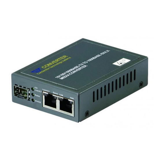
Converter. The built-in management module allows users to configure this Managed Converter and monitor the operation status locally. 1.1 Front Panel & Real Panel Figure 1: CVT-3012SFP Front Panel Figure 2: CVT-3012SFP Rear Panel 1.2 Management Preparations Before you can manage your Managed Converter locally, you need to use the appropriate network cable to connect your converter. -
Page 5: Management Option - Local Console Management
available with a “copper” cable interface, allowing a host device designed primarily for optical fiber communications to also communicate over unshielded twisted pair networking cable. SFP slot for 3.3V mini GBIC module supports hot swappable SFP fiber transceiver. Before connect the other switches, workstation or Media Converter, make sure both side of the SFP transfer are with the same media type, for example: 1000Base-SX to 1000Base-SX, 1000Bas-LX to 1000Base-LX and check that the fiber-optic cable type matches the SFP transfer model. -
Page 6: Led Definitions
1.4 LED Definitions Color Function Green Lit when power is available. TP/Link Act Green Lit when TP cable connection with the remote device is good. Blink when TP traffic is present. Orange Blink when Fiber or Copper link is down in Link Alarm-enabled mode. -
Page 7: Console Program
2. CONSOLE PROGRAM This chapter describes how to access to the Managed Converter and use its local Console program (out-of-band). The interface and options of the Console program are same as Telnet Management. The difference is the type of connection and the port that is used to manage the converter. -
Page 8: Console Program Overview
2.2 Console Program Overview Once you gain the access, the Main menu appears. 2.3 Navigating the Console Program Screen Use this key… To do this… Enter the number key directly To enter each menu Press ESC To exit the current screen 2.4 Port Status Port Status allows users to monitor the real-time port operation status of the Managed Converter. -
Page 9: Current Configuration Status
Speed: View-only field that shows the current operation speed of the port (10M, 100M or 1000M). Duplex: View-only field that shows the current Duplex mode of the port (could be Full or Half). 2.5 Current Configuration Status In order to view the current configurations of the Managed Converter, press “01” to enter Current Configuration Status from the Main menu. -
Page 10: System Information
ISP: View-only field that shows the current ISP port. “En” means Enable and denotes that the port is the ISP port. “Dis” means Disable and denotes that the port is not the ISP port. ISP_Tag: View-only field that shows the current ISP tag value. 2.6 System information In order to view the Hardware and Firmware information of the Managed Converter, press “02”... - Page 11 SFP Module Information: Identifier: View-only field that shows whether the SFP slot has detected the SFP module or not. Connector: View-only field that shows the SFP connector type. Compliance I/F: View-only field that shows the Slide-in SFP module Interface. Encoding: View-only field that shows the slide-in SFP module Encoding code. Vendor Name: View-only field that shows the slide-in SFP module vendor name.
-
Page 12: Qinq Configuration
TX Power (mw): View-only field that shows the Slide-in SFP module’s optical transmission power. RX Power (mw): View-only field that shows the Slide-in SFP module’s optical receiver power. 2.8 QinQ Configuration Press “04” to enter QinQ Configuration from the Main menu to configure Q-in-Q double tag VLAN settings. -
Page 13: Qinq Mode
2.8.1 QinQ Mode Press “1” to enter QinQ Mode and set up Ether Type, ISP Tag and ISP Port. 1. Specify Ether Type: Specify Ether Type such as 9100, 9200, 9300 or a user-defined Ether type value. 2. Specify ISP Tag (Dec): Specify a value between 1 and 4095. -
Page 14: Load Default Factory Settings
3. Select ISP Port: Select TP or FX as an ISP port. 2.9 Load Default Factory Settings Press “05” to enter Load Default Factory Settings from the Main menu, then the following screen appears. Load Default Factory Settings: Load Factory Settings will return the configurations of the Managed Converter back to the factory default settings. -
Page 15: System Reset
2.10 System Reset Press “06” to enter System Reset from the Main menu, then the following screen appears. To reset or restart the Managed Converter, press “1” and then press Enter to perform the reset. 2.11 Firmware Upgrade (Xmodem) Press “07” to enter Firmware Upgrade (Xmodem) from the Main menu, then the following screen appears. - Page 16 Press “1” to process Firmware upgrade. Select Transfer and then select Send file from the drop-down menu. Enter the Filename and select the Protocol Filename: Enter the specific path and filename. Protocol: Select Xmodem Protocol. Transmit the Firmware file to the Managed Converter. After the update is successful, the Managed Converter will be reset automatically.
-
Page 17: Port Mirror Configuration
2.12 Port Mirror Configuration Press “08” to enter Port Mirror Configuration from the Main menu, then the following screen appears. 0 <Disable Mirror>: The port mirroring function is disabled by default. Enter “0” to disable port mirroring manually. 1 <Source FX, Target TP>: A copy of packets from TX port will be sent to TP port. Please refer to 2.12.1 Source FX, Target TP section. -
Page 18: Source Tp, Target Fx
0: Specify 0 to send a copy of ingress packets from FX port to Target TP port; however, packets from Target port will not be forwarded to Source Port. 1: Specify 1 to send a copy of ingress packets from FX port to Target TP port. Packets from Target port will also be forwarded to Source Port. - Page 19 This page is intentionally left blank. Revision History Manual Version Modification Firmware Version Date Modify LOGO image 1.04.00 2010/11 Revise the NMS Manual 1.04.00 2009/11 Add Port Mirror Configuration section Note: This User’s Manual is written or revised according to the officially-released Firmware version. The content of this Manual is subject to change without prior notice.
Need help?
Do you have a question about the CVT-3012SFP and is the answer not in the manual?
Questions and answers