
Related Manuals for CTS HES-3112-CL-DR SERIES


Summary of Contents for CTS HES-3112-CL-DR SERIES
- Page 1 HES-3112-CL-DR SERIES 10/100/1000BASE-T RJ45 and 100/1000BASE-X SFP Combo to 100/1000BASE-X ETHERNET MANAGED MEDIA CONVERTER Network Management User’s Manual Version 1.0...
-
Page 2: Fcc Warning
Trademarks CTS is a registered trademark of Connection Technology Systems Inc.. Contents subject to revision without prior notice. All other trademarks remain the properties of their owners. Copyright Statement Copyright 2013 Connection Technology Systems Inc.. This publication may not be reproduced as a whole or in part, in any way whatsoever unless prior consent has been obtained from Connection Technology Systems Inc.. -
Page 3: Table Of Contents
Table of Content 1. INTRODUCTION ....................... 6 1.1 Interfaces........................6 1.2 Management Preparations ................... 7 1.2.1 Connecting the Managed Media Converter ............7 1.2.2 Assigning IP Addresses ..................7 1.3 LED Definitions ......................8 1.4 Button Definitions ......................8 2. Command Line Interface (CLI) ..................9 2.1 Remote Console Management-Telnet ................ - Page 4 2.5.11 SNMP-Server Command ................... 28 2.5.12 Switch Command ....................31 2.5.13 Switch-info Command ..................31 2.5.14 User Command ....................32 2.5.15 VLAN Command ....................34 2.5.16 Show interface statistics Command ..............36 2.5.17 Show sfp Command ................... 37 2.5.18 Show log Command................... 37 2.5.19 Show default-config, running-config and start-up-config Command ....
- Page 5 3.5.1 Converter Port State .................... 66 3.5.2 Port Counters Rates .................... 67 3.5.2.1 Port Traffic Statistics (Rates) ................. 68 3.5.2.2 Port Packet Error Statistics (Rates) ............... 68 3.5.2.3 Port Packet Analysis Statistics (Rates) ............69 3.5.3 Port Counters Events ................... 70 3.5.3.1 Port Traffic Statistics (Events) ...............
-
Page 6: Introduction
1. INTRODUCTION Thank you for using the 10/100/1000BASE-T RJ45 or 1000BASE-X SFP to 100/1000BASE-X ETHERNET MANAGED MEDIA CONVERTER. The Managed Media Converter is fully compliant with IEEE 802.3, 802.3u, 802.3z and 802.3ab standards. By employing store and forward switching mechanism, the Media Converter provides low latency and faster data transmission. -
Page 7: Management Preparations
1.2 Management Preparations The Managed Media Converter can be accessed through both Telnet connection and a web browser, such as Internet Explorer or Netscape, and etc.. Before you can access the Managed Media Converter to configure it, you need to connect cables properly. 1.2.1 Connecting the Managed Media Converter It is extremely important that proper cables are used with correct pin arrangements when connecting Managed Media Converter to other devices such as switches, hubs, workstations,... -
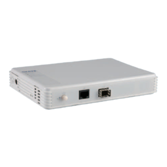
Page 8: Led Definitions
A subnet mask is a filtering system for IP addresses. It allows you to further subdivide your network. You must use the proper subnet mask for a proper operation of a network with subnets defined. 1.3 LED Definitions Definition Color Operation The device is powered off. -
Page 9: Command Line Interface (Cli)
2. Command Line Interface (CLI) This chapter guides you to use Command Line Interface (CLI) via Telnet connection, specifically in: Configuring the system Resetting the system Upgrading newly released firmware 2.1 Remote Console Management-Telnet You can use Command Line Interface to manage the Managed Media Converter via Telnet session. -
Page 10: Navigating Cli
2.2 Navigating CLI After you successfully access to the Managed Media Converter, you will be asked for a login username. Enter your authorized username and password, and then you will be directed to the User Mode. In CLI management, the User Mode only provides users with basic functions to operate the Managed Switch. -
Page 11: Quick Keys
2.2.2 Quick Keys In CLI, there are several quick keys that you can use to perform several functions. The following table summarizes the most frequently used quick keys in CLI. Keys Purpose Enter an unfinished command and press “Tab” key to complete the command. - Page 12 The following table lists common symbols and syntax that you will see very frequently in this User‟s Manual for your reference: Symbols Brief Description > Currently, the device is in User Mode. Currently, the device is in Privileged Mode. Currently, the device is in Global (config)# Configuration Mode.
-
Page 13: Login Username & Password
2.2.4 Login Username & Password Default Login After you enter Telnet session, a login prompt will appear to request a valid and authorized username and password combination. For first-time users, enter the default login username “admin” and “press Enter key” in password field (no password is required for default setting). When system prompt shows “Converter>”, it means that the user has successfully entered the User Mode. -
Page 14: Privileged Mode
2.4 Privileged Mode The only place where you can enter the Privileged (Enable) Mode is in User Mode. When you successfully enter Enable mode, the prompt will be changed to Converter# (the model name of your device together with a pound sign). Enter the question mark (?) or help command to view a list of commands available for use. -
Page 15: Firmware Command
3. Restore the Managed Media Converter back to default settings but keep IP configurations. Command / Example Converter# copy-cfg from default keep-ip 4. Backup a configuration file to FTP/TFTP server. Command Parameter Description Converter# copy- [A.B.C.D] Enter the IP address of your FTP server. cfg to ftp [A.B.C.D] Enter the configuration file name that you want to [file_name]... -
Page 16: Write Command
2.4.4 Write Command To save running configurations to startup configurations, enter the write command. All unsaved configurations will be lost when you restart the Managed Media Converter. Command / Example Converter# write 2.4.5 Configure Command You can enter Global Configuration Mode only from Privileged Mode. You can type in “configure”... -
Page 17: Entering Interface Numbers
2.5.1 Entering Interface Numbers In the Global Configuration Mode, you can configure a command that is only applied to interfaces specified. For example, you can set up each interface‟s VLAN assignment, speed, or duplex mode. To configure, you must first enter the interface number. There are four ways to enter your interface numbers to signify the combination of different interfaces that apply to a command or commands. - Page 18 This is only applicable to the LAN port. Set up the combo mode for the LAN port. [fiber-priority]: Both fiber and copper LAN ports are available, but when both interfaces are detected, fiber will be the transmission medium. Converter(config-if-PORT)# [fiber-priority | combo-mode [fiber-priority | copper-priority [copper-priority]: Both fiber and copper LAN...
-
Page 19: Ip Command
Interface Command Example Converter(config)# interface 1 Configure LAN interface. Converter(config)# interface 1,2 Configure both LAN and WAN interfaces. Converter(config-if-1)# auto-negotiation Set LAN interface to auto-negotiation. Converter(config-if-1)# Set LAN interface‟s combo mode to fiber- priority mode. combo-mode fiber-priority Converter(config-if-1)# duplex full Set LAN interface to full duplex mode. -
Page 20: Mac Command
3. Configure IP source binding function. IP Command Parameter Description Converter(config)# ip source Enable IP source binding function. Converter(config)# [1-12] Enable the specified entry. ip source binding [1-12] Converter(config)# Set up the IP address for the specified ip source binding [1-12] ip- [port_list] entry. -
Page 21: Management Command
2.5.7 Management Command Management Command Parameter Description Converter(config)# management Enable SSH, telnet or Web GUI [ssh | telnet | [ssh | telnet | web] management interface. web] No Command Converter(config)# no [ssh | telnet | Disable SSH, telnet or Web GUI management [ssh | telnet | web] web] management interface. -
Page 22: Qos Command
Show Command Converter(config)# show ntp Show or verify current time server settings. NTP Command Example Enable the Managed Converter to Converter(config)# ntp synchronize the clock with a time server. Set the primary time server IP address to Converter(config)# ntp server1 192.180.0.12 192.180.0.12. - Page 23 3. Set up management traffic priority. Management-Priority Command Parameter Description Converter(config)# qos Specify management traffic default [0-7] management-priority [0-7] 802.1p priority bit. No command Set management traffic priority back to Converter(config)# no qos management-priority the default. Management-Priority Example Converter(config)# qos management-priority 4 Set management traffic priority to 4.
- Page 24 5. Set up queue weight. Queuing-Weighted Command Parameter Description By default, queuing weight is “1:2:4:8”. Converter(config)# qos queuing- [ _:_:_:_ ] weighted [1:2:4:8] (1-32) Specify the value from 1 to 32. No Command Converter(config)# no qos queuing-weighted Set the queuing weight back to the default.
- Page 25 VID Remarking command Configure the mapping of VID remarking Converter(config)# qos remarking mode. [1-8] vid-map [1-8] [1-8]: Select the mapping entry Converter(config-vid-map-ID)# Enable the mapping entry. active Converter(config-vid-map-ID)# [1-4094] Specify the VLAN to be remarked. vlan-id [1-4094] Converter(config-vid-map-ID)# [0-7] Specify the 802.1p remarking value. priority [0-7] Converter(config-vid-map-ID)# Exit the entry.
- Page 26 8. Assign a tag priority to the specific queue. 802.1p-map Command Parameter Description Assign one or several 802.1p priority bits for mapping. Set up the corresponding priority value [0-7] Converter(config)#qos 802.1p- 802.1p_list map [0-7] 802.1p_list [0-3] Priority Normal Medium High Level 802.1p Value...
-
Page 27: Security Command
Show Command Converter(config)# show qos Show or verify the selected interfaces‟ [port_list] interface [port_list] ingress and egress rate configurations. Show or verify each interface‟s ingress Converter(config)# show qos interface and egress rate configurations. Converter(config)# show qos Show or verify QoS configurations. QoS &... -
Page 28: Snmp-Server Command
2.5.11 SNMP-Server Command 1. Create a SNMP community and set up detailed configurations for this community. Snmp-Server Command Parameter Description Converter(config)# snmp- Specify a SNMP community name up to 20 [community] server community [community] alphanumeric characters. Converter(config-community- Enable this SNMP community account. NAME)# active Converter(config-community- Enter the description up to 35... - Page 29 Snmp-Server Example Create a new community “mycomm” and Converter(config)# snmp-server community mycomm edit the details of this community account. Converter(config-community-mycomm)# Activate the SNMP community “mycomm”. active Add a description for “mycomm” Converter(config-community-mycomm)# description rddeptcomm community. Converter(config-community-mycomm)# level Set “mycomm” community level to admin. admin 2.
- Page 30 Converter(config-trap-1)# description Add a description for this trap destination redepttrapdest account. Converter(config-trap-1)# destination Set trap destination IP address to 172.168.1.254 192.168.1.254. 3. Set up SNMP trap types that will be sent. Trap-Type Command Parameter Description Specify the trap type that will be sent when a certain situation occurs.
-
Page 31: Switch Command
2.5.12 Switch Command Switch Command Description Enable link alarm function. Converter(config)# switch link-alarm Enable the Converter to refresh SFP DMI Converter(config)# switch sfp polling information and current state in a fixed interval. Converter(config)# switch statistics Enable the Converter to refresh counter polling information and current state in a fixed interval. -
Page 32: User Command
Enter a unique name up to 55 alphanumeric characters for this Managed Converter. Use Converter(config)# switch- a descriptive name to identify the Managed info system-name [system_name] Converter in relation to your network, for [system_name] example, “Backbone 1”. This name is mainly used for reference only. - Page 33 Specify user account level. By default, when you create a community, the access privilege for this account is set to “read only”. Admin: Full access right, including Converter(config-user- maintaining user account, system [admin | rw | USERNAME)# level [admin | information, loading factory settings, etc..
-
Page 34: Vlan Command
2.5.15 VLAN Command Set up 802.1q VLAN, port-based VLAN, management VLAN and Q-in-Q VLAN. VLAN Command Parameter Description Converter(config)# vlan dot1q- Enable 802.1q VLAN mode. vlan Converter(config)# vlan dot1q- Enter a VID number to create a 802.1q [1-4094] vlan [1-4094] VLAN. - Page 35 Converter(config-if-PORT)# vlan dot1q-vlan mode trunk Enable native VLAN for untagged traffic. native Converter(config-if-PORT)# Add the selected port to the specified port [name] vlan port-based [name] based VLAN. Converter(config-if-PORT)# Specify the service tag VID for the selected [1-4094] vlan qinq-vlan stag-vid [1-4094] port.
-
Page 36: Show Interface Statistics Command
VLAN dot1q & interface example Converter(config)# vlan dot1q-vlan 100 Create a new VLAN 100. Set VLAN 200 to be the management Converter(config)# vlan management-vlan VLAN, and WAN port to be the 200 management-port 2 management port. Converter(config)# interface 1 Enter LAN interface. Converter(config-if-1,2)# vlan dot1q-vlan Assign the LAN and WAN ports to be the trunk-vlan 100... -
Page 37: Show Sfp Command
2.5.17 Show sfp Command When you slide in SFP transceiver, detailed information about this module can be viewed by issuing this command. Command Description Display the slide-in SFP information Converter(config)# show sfp information including speed, distance, vendor name, vendor PN and vendor serial number. Display the slide-in SFP information Converter(config)# show sfp state including temperature, voltage, TX bias, TX... -
Page 38: Web Management
3. WEB MANAGEMENT The Managed Converter can be managed via a Web browser. The default IP of the Managed Converter can be reached at “http://192.168.0.1”. You can change the Converter‟s IP address to the intended one later in its Network Management menu. Follow these steps to manage the Managed Converter through a Web browser: 1. - Page 39 After a successful login, the screen appears as below. 1. System Information: Name the Managed Converter, specify the location and check the current version of information. 2. User Authentication: Create and view the registered user list. 3. Network Management: Set up or view the IP address and related information about the Managed Converter required for network management applications.
-
Page 40: System Information
3.1 System Information Select System Information from the left column and then the following screen shows up. Company Name: Enter a company name up to 55 alphanumeric characters for this Managed Converter. System Object ID: View-only field that shows the predefined System OID. System Contact: Enter contact information up to 55 alphanumeric characters for this Managed Converter. - Page 41 Model Name: View-only field that shows the product‟s model name. Host Name: View-only field that shows the product‟s host name. Firmware Version: View-only field that shows the product‟s firmware version. 1000M Port Number: The number of ports transmitting at the speed of 1000Mbps 100M Port Number: The number of ports transmitting at the speed of 100Mbps M/B Version: View-only field that shows the main board version.
-
Page 42: User Authentication
3.2 User Authentication To prevent any un-authorized operation, only registered users are allowed to operate the Managed Converter. Users who want to operate the Managed Converter need to register into the user‟s list first. To view or change current registered users, select User Authentication from the left column and then the following screen page shows up. - Page 43 Account State: Enable or disable the selected account. User Name: Specify the authorized user login name, up to 20 alphanumeric characters. Password: Enter the desired user password, up to 20 alphanumeric characters. Retype Password: Enter the password again to confirm. Description: Enter a unique description up to 35 alphanumeric characters for this user.
-
Page 44: Network Management
3.3 Network Management In order to enable network management of the Managed Converter, proper network configuration is required. To do this, click the folder Network Management from the left column and then the following screen page appears. 1. Network Configuration: Set up the required IP configuration of the Managed Converter. 2. -
Page 45: Network Configuration
3.3.1 Network Configuration Click the option Network Configuration from the Network Management menu and then the following screen page appears. MAC Address: This view-only field shows the unique and permanent MAC address pre- assigned to the Managed Converter. You cannot change the Managed Converter‟s MAC address. - Page 46 IP Source Binding Source Binding: Enable or disable IP Source Binding function. This function allows the specified IP addresses to access the device. State: Enable or disable the entry. IP Address: Specify the IP address of the entry. Click the “OK” button to apply the settings.
-
Page 47: System Service Configuration
3.3.2 System Service Configuration Click the option System Service Configuration from the Network Management menu and then the following screen page appears. Telnet Service: Select disabled, Telnet or SSH for the Telnet service type. SNMP Service: Enable or disable SNMP management interface Web Service: Enable or disable Web GUI management interface. -
Page 48: Device Community
maximum value is 24 hours. Time Zone: Select the appropriate time zone from the pull-down menu. Click the “OK” button to apply the settings. 3.3.4 Device Community Click the option Device Community from the Network Management menu and then the following screen page appears. -
Page 49: Trap Destination
Max Agents: This shows the number of maximum number available for registration. The default maximum number is 3. Account State: Enable or disable this Community Account. Community: Specify the authorized SNMP community name, up to 20 alphanumeric characters. Description: Enter a unique description up to 35 alphanumeric characters for this community name. -
Page 50: Trap Configuration
3.3.6 Trap Configuration Click the option Trap Configuration from the Network Management menu and then the following screen page appears. Cold Start Trap: Enable or disable the Managed Converter to send a trap when the Managed Converter cold starts. Warm Start Trap: Enable or disable the Managed Converter to send a trap when the Managed Converter warm starts. -
Page 51: Converter Management
3.4 Converter Management To manage the Managed Converter and set up required functions, click the folder Converter Management from the left column and then several options and folders will be displayed for your selection. 1. Converter Configuration: Set up address learning aging time and enable or disable IGMP Snooping and Fast Leave. -
Page 52: Converter Configuration
3.4.1 Converter Configuration Click the option Converter Configuration from the Converter Management menu and then the following screen page appears. MAC Address Aging Time: Set up MAC Address aging time manually. Entries in the MAC address table containing source MAC addresses and their associated ports will be deleted if they are not accessed within the aging time. -
Page 53: Port Configuration
Storm Rate Bandwidth: Display the current configured storm rate bandwidth. Click the “OK” button to apply the settings. 3.4.3 Port Configuration Click the option Port Configuration from the Converter Management menu and then the following screen page appears. Port Number: Click the pull-down menu to select the port number for configuration. Port Combo Mode: There are four options for the combo mode, Fiber-Priority, Copper Priority, Fiber-Only and Copper-Only. -
Page 54: Rate Limit Configuration
3.4.4 Rate Limit Configuration Click the folder Rate Limit Configuration from the left column and then the following screen page appears. Ingress Rate: Click the pull-down menu to set up Port Ingress Rate, on or off. Ingress Limiter: Enter ingress bandwidth for each port (the allowable bandwidth is between 32 and 1000000). -
Page 55: Qos Priority Configuration
3.4.5 QoS Priority Configuration Network traffic is always unpredictable and the only basic assurance that can be offered is the best effort traffic delivery. To overcome this challenge, Quality of Service (QoS) is applied throughout the network. This ensures that network traffic is prioritized according to specified criterion and receives preferential treatments. - Page 56 The default value is “0”. The default 802.1p settings are shown in the following table: Priority Level Normal Medium Medium High High 802.1p Value DSCP Priority Map: Select priority queue mapping for the DSCP field of every IP packet from the pull-down menu. The DSCP includes DSCP (0) to DSCP (63), and the priority queue includes Q0, Q1, Q2 and Q3.
- Page 57 802.1p Remarking State: Disable or enable the mapping entry. RX-802.1p: Specify the 802.1p value to be remarked. New-802.1p: Specify the remarking 802.1p value. VID + 802.1p Remarking...
- Page 58 DSCP Remarking: Enable or disable 802.1p Remarking. State: Disable or enable the mapping entry. RX-DSCP: Specify the DSCP value to be remarked. New-DSCP: Specify the remarking DSCP value. Click the “OK” button to apply the settings. Note: The VID remarking has higher priority than the other remarking modes. (VID remarking >...
-
Page 59: Vlan Configuration
3.4.6 VLAN Configuration A Virtual Local Area Network (VLAN) is a network topology configured according to a logical scheme rather than the physical layout. VLAN can be used to combine any collections of LAN segments into a group that appears as a single LAN. VLAN also logically segments the network into different broadcast domains. -
Page 60: Port Based Vlan
Click the folder VLAN Configuration from the Converter Management folder and then the following screen page appears. 1. Port Based VLAN: Configure Port-Based VLAN settings. 2. IEEE 802.1Q Tag VLAN: Configure IEEE 802.1Q Tag VLAN settings. 3. QinQ VLAN Configuration: Configure Q-in-Q VLAN settings. 3.4.6.1 Port Based VLAN Click the folder Port Based VLAN from the VLAN Configuration menu and then the following screen page appears. -
Page 61: Configure Vlan
3.4.6.1.1 Configure VLAN Click the option Configure VLAN from the Port Based VLAN folder and then the following screen page appears. Click Edit to view and edit current Port Based VLAN setting, and then the following screen page appears. Click Delete to remove a VLAN entity. Port Name: View-only field that shows the name of the port based VLAN VLAN Members: Select the member ports of the port based VLAN... -
Page 62: Ieee 802.1Q Tag Vlan
3.4.6.2 IEEE 802.1q Tag VLAN Click the folder IEEE 802.1Q Tag VLAN from the VLAN Configuration menu and then the following screen page appears. 1. Configure VLAN: To create, edit, delete, or apply 802.1Q Tag VLAN settings. 2. Configure Default Port VLAN ID: To set up 802.1q Port VLAN ID. 3.4.6.2.1 Configure VLAN Click the option Configure VLAN from the IEEE 802.1q Tag VLAN menu and then the following screen page appears. -
Page 63: Configure Default Port Vlan Id
Current/Total/Max VLANs: View-only field. Current: This shows the number of currently registered VLAN. Total: This shows the number of total registered VLANs. Max: This shows the maximum number of available VLANs to be registered. VLAN ID: Specify the ID for the currently registered VLAN. VLAN Name: Specify the name for the currently registered VLAN. -
Page 64: Q-In-Q Vlan Configuration
Port VLAN Mode: Set up egress traffic as untagged or tagged. Mode Port Behavior Receive untagged packets only. Drop tagged packets. Access Send untagged packets only. Receive tagged packets only. Drop untagged packets. Trunk Send tagged packets only. Receive both untagged Untagged packets: PVID is added and tagged packets Tagged packets: Stay intact... -
Page 65: Filter Configuration
Pass Through VID: Specify the Pass Through VLAN ID. Click the “OK” button to apply the settings. 3.4.7 Filter Configuration Click the option Filter Configuration from the Converter Management menu and then the following screen page appears. DHCP Snooping: Enable or disable DHCP Snooping function. DHCP Server Trust Port: Assign the specific port(s) to be the DHCP Server Trust Port(s). -
Page 66: Converter Monitor
3.5 Converter Monitor Converter Monitor allows users to monitor the real-time operation status of the Managed Converter. Users may monitor the port link-up status or traffic counters for maintenance or diagnostic purposes. Select the folder Converter Monitor from the Main Menu and then the following screen page appears. -
Page 67: Port Counters Rates
Port Sate: This shows each port‟s state which can be E (Enabled) or D (Disabled). Enabled: Packets can be forwarded. Disabled: A port in this state can not receive and forward packets. Link State: The current link status of the port, either up or down. Speed (Mbps): The current operation speed of each port. -
Page 68: Port Traffic Statistics (Rates)
3.5.2.1 Port Traffic Statistics (Rates) The following screen page appears if you choose Port Counters Rates and then select Port Traffic Statistics (Rates). Bytes Received: Total bytes received from each port. Frames Received: Total frames received from each port. Received Utilization: The ratio of each port‟s receiving traffic to current port‟s total bandwidth. Bytes Sent: The total bytes sent from current port. -
Page 69: Port Packet Analysis Statistics (Rates)
RX Jabbers: Jabber frames received. TX Collisions: Total frames collision detected. Total Errors: The number of total errors occurred. 3.5.2.3 Port Packet Analysis Statistics (Rates) The following screen page appears if you choose Port Counters Rates and then select Port Packet Analysis Statistics (Rates). -
Page 70: Port Counters Events
3.5.3 Port Counters Events The event mode of port counters will be re-calculated when that counter is reset or cleared. Click Port counters Events folder and then three options appear. 1. Port Traffic Statistics (Events): View the number of bytes received, frames received, bytes sent, frames sent, and total bytes and clear each row‟s statistics. -
Page 71: Port Packet Error Statistics (Events)
Total Bytes: Total bytes received and sent from current port. Click “Clear All” button to clear all ports‟ statistics. 3.5.3.2 Port Packet Error Statistics (Events) The following screen page appears if you choose Port Counters Events and then select Port Packet Error Statistics (Events). RX CRC Error: The number of packets received with a bad FCS with an integral number of bytes. -
Page 72: Port Packet Analysis Statistics (Events)
3.5.3.3 Port Packet Analysis Statistics (Events) The following screen page appears if you choose Port Counters Events and then select Port Packet Analysis Statistics (Events). RX Frames 64 Bytes: 64 bytes frames received. RX Frames 65-128 Bytes: 65-128 bytes frames received. RX Frames 129-256 Bytes: 129-256 bytes frames received. -
Page 73: Sfp Information
3.5.4 SFP Information Click SFP Information folder from the left column and then two options appear. SFP Port Info: This shows the information of Speed, Distance, Vendor Name, Vendor PN, and Vendor SN of the SFP Port. SFP Port State: This shows the state of Temperature, Voltage, TX Bias, TX Power, and RX Power of the SFP Port. -
Page 74: Sfp Port State
3.5.4.2 SFP Port State The following screen page appears if you choose SFP Information and then select SFP Port State. Port: The port number of the slide-in SFP module. Temperature (C): The Slide-in SFP module operation temperature. Voltage (V): The slide-in SFP module operation voltage. TX Bias (mA): The slide-in SFP module operation current. -
Page 75: System Utility
3.6 System Utility Select the folder System Utility from the left column and then the following screen page appears. 1. Event Log: Event log can keep a record of system‟s log events such as system warm start, cold start, link up/down, user login/logout, etc.. 2. -
Page 76: Event Log
3.6.1 Event Log Event log keeps a record of user login and logout timestamp information. Select Event Log from the System Utility menu and then the following screen page appears. The Event Log table stores the latest 500 logs in the Managed Converter. Click “Clear All”... -
Page 77: Load Factory Settings
User Name: Enter the specific username to access the File Server. Password: Enter the specific password to access the File Server. File Location: Enter the specific path and filename within the File Server. Put: Click “Put” button to start the upload process and transmit the configuration file to the server. -
Page 78: Load Factory Settings Except Network Configuration
3.6.4 Load Factory Settings Except Network Configuration Load Factory Settings Except Network Configuration will set all configurations of the Managed Converter back to the factory default settings. However, IP and Gateway addresses will not restore to the factory default. Load Factory Settings Except Network Configuration is very useful when network administrators need to re-configure the system “REMOTELY”... -
Page 79: Reset System
3.8 Reset System After any configuration changes, Reset System can make changes effective. Select Reset System from the Main menu and then the following screen page appears. Click the “OK” button to restart the Managed Converter. 3.9 Logout Select Logout from the Main menu and then the following screen page appears. Click the “OK”... -
Page 80: Appendix A: Dhcp Auto-Provisioning Setup
APPENDIX A: DHCP Auto-Provisioning Setup Networking devices, such as converters, switches or gateways, with DHCP Auto-provisioning function allow you to automatically upgrade firmware and configuration at startup process. Before setting up DHCP Server for auto-upgrade of firmware and configuration, please make sure the Managed Converter that you purchased supports DHCP Auto-provisioning. - Page 81 Step 2. Set Up Auto Provision Server Update DHCP client Linux Fedora 12 supports “yum” function by default. First of all, update DHCP client function by issuing “yum install dhclient” command. Install DHCP server Issue “yum install dhcp” command to install DHCP server.
- Page 82 Copy dhcpd.conf to /etc/dhcp/ directory Copy dhcpd.conf file provided by the vendor to /etc/dhcp/ directory. Please note that each vendor has its own way to define auto-provisioning. Make sure to use the file provided by the vendor. Enable and run DHCP service 1.
- Page 83 Step 3. Modify dhcpd.conf File Open dhcpd.conf file in /etc/dhcp/ directory Double-click dhcpd.conf placed in /etc/dhcp/ directory to open it.
- Page 84 Modify dhcpd.conf file The following marked areas in dhcpd.conf file can be modified with values that work with your networking environment. 1. Define DHCP default and maximum lease time in seconds. Default lease time: If a client does not request a specific IP lease time, the server will assign a default lease time value.
- Page 85 5. This value is configurable and can be defined by users. 6. Specify the protocol used (Protocol 1: FTP; Protocol 0: TFTP). 7. Specify the FTP or TFTP IP address. 8. Login TFTP server anonymously (TFTP does not require a login name and password). 9.
- Page 86 Restart DHCP service...
- Page 87 Every time you modify dhcpd.conf file, DHCP service must be restarted. Issue “killall dhcpd” command to disable DHCP service and then issue “dhcpd” command to enable DHCP service. Step 4. Backup a Configuration File Before preparing a configuration file in TFTP/FTP Server, make sure the device generating the configuration file is set to “Get IP address from DHCP”...
- Page 88 B. Auto-Provisioning Process This device is setting-free (through auto-upgrade and configuration) and its upgrade procedures are as follows: 1. ISC DHCP server will recognize the device when it receives an IP address request sent by the device, and it will tell the device how to get a new firmware or configuration. 2.
- Page 89 This page is intentionally left blank. Manual Version Modification Firmware Version Date The initial version 1.00.00 201305...
Need help?
Do you have a question about the HES-3112-CL-DR SERIES and is the answer not in the manual?
Questions and answers