Table of Contents
Advertisement
IMPORTANT: RECEIVING INSTRUCTIONS
Visually inspect all components for shipping damage. If you find damage, notify the carrier at once.
Shipping damage is NOT covered by warranty. The carrier is responsible for all repair or replacement costs resulting from damage in shipment.
Read this owners manual thoroughly before use and save.
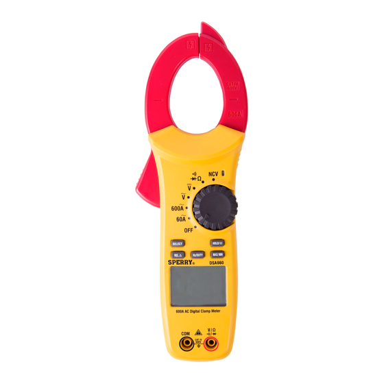
Rotary Switch
NCV
Non-Contact Voltage Measurement
Continuity Test/Diode Test/
Resistance Measurement
DC Voltage Measurement
A
400A
AC Voltage Measurement
A
400A
600
A
AC Current Measurement
A
400A
60
A
AC Current Measurement
A
OFF
Power Off
A
A
400A
A
A
Clamp
Trigger
Function
Relative
LCD
COM
Function Selection
BUTTON
SELECT
REL
Hz/DUTY
MAX/MIN
HOLD/
OPERATING INSTRUCTIONS
Digital Clamp Meter
DSA660
Rotary Switch
HOLD / Backlight
MAX/MIN
Frequency / Duty Cycle
Input
Figure 1
OPERATION PERFORMED
Switch between Continuity, Diode, and Resistance at the
Display the difference between the measured value and the stored value
on the LCD screen
Measure Frequency / Measure Duty Cycle
Retain the highest or lowest measurement value being recorded
Retain the measured value on the LCD screen / Turn on display backlight
1
measurement settings
Advertisement
Table of Contents

Related Manuals for Sperry instruments DSA660


Summary of Contents for Sperry instruments DSA660
-
Page 1: Operating Instructions
OPERATING INSTRUCTIONS Digital Clamp Meter DSA660 IMPORTANT: RECEIVING INSTRUCTIONS Visually inspect all components for shipping damage. If you find damage, notify the carrier at once. Shipping damage is NOT covered by warranty. The carrier is responsible for all repair or replacement costs resulting from damage in shipment. -
Page 2: Safety Warnings
Display Symbols Auto Power Off Relative Hz, kHz, Hertz, Kilohertz, Continuity Indication Measurement Megahertz (Frequency) Non-contact Diode Check Data Hold Duty Cycle Voltage Detection — mV, V Maximum value Negative Value Millivolt, Volt Low Battery Amperes, Milliamp, Minimum value Direct Current µA,mA, A Overload Microamp (Current) - Page 3 DANGER • Never make measurement on a circuit in which voltage over 600V exists. • Do not exceed the CAT rating of the measuring device. • Do not attempt to make measurement in the presence of flammable gases. The use of the instrument may cause sparking, which can lead to an explosion. •...
-
Page 4: Specification
3. SPECIFICATION 3-1. Measuring range & accuracy (Accuracy guaranteed at 23°C ± 5°C, humidity <80%) AC CURRENT RESISTANCE RANGE RESOLUTION ACCURACY RANGE RESOLUTION ACCURACY 0.1A 600Ω 0.1Ω ± (2.0% + 9) 6KΩ 0.001kΩ ± (1.2% + 5) 600A 60KΩ 0.01kΩ - Main Display: Average Current 600KΩ... -
Page 5: Preparation For Measurement
3-2. General Specification • The maximum voltage allowed between terminal and ground: 600 VDC or 600 VAC • Altitude: Maximum 2000m • Display: 5999 count • Sampling time: ~ 2.5 times / sec • Automatic power off: 15 Minutes (Unless disabled) •... -
Page 6: Continuity Test
CONTINUITY TEST 1. Insert test leads – Insert the black test lead into the COM input and the red test lead into the input. 2. Set function – Turn the dial to the function. 3. Select Function – There are a total of 3 functions that are accessible by pressing the SELECT key. Press the SELECT key until appears on the display. -
Page 7: Duty Cycle
5-4. Frequency/Duty Cycle FREQUENCY HZ 1. Set Hz function – Set the meter for an AC voltage or current measurement and press the Hz/DUTY button. Hz should be shown on the display. 2. Test & Measure – Place the red and black test leads at both the positive and negative points to be measured. The display will show the value of the frequency measurement being taken. -
Page 8: Polarity Indication
6-9. Polarity indication 1. The meter displays “-” for negative values, positive is implied 6-10. Over Range indication 1. When the input exceeds the measuring range “OL” is displayed on the LCD screen 6-11. Non-contact Voltage (NCV) Detection WARNING • Test on a known live source before use •... -
Page 9: Lifetime Warranty
Sperry’s written instructions. Test leads, fuses, batteries and calibration are not covered under any implied warranty. “Lifetime” of products that are no longer offered by Sperry will be either repaired or replaced with an item of Sperry Instruments choice of similar value. Lifetime is defined as 5 years after Sperry discontinued manufacturing the product, but the warranty period shall be at least ten years from date of purchase.
Need help?
Do you have a question about the DSA660 and is the answer not in the manual?
Questions and answers