Advertisement
Quick Links
ISO Registered Company
I.
DESCRIPTION AND SCOPE
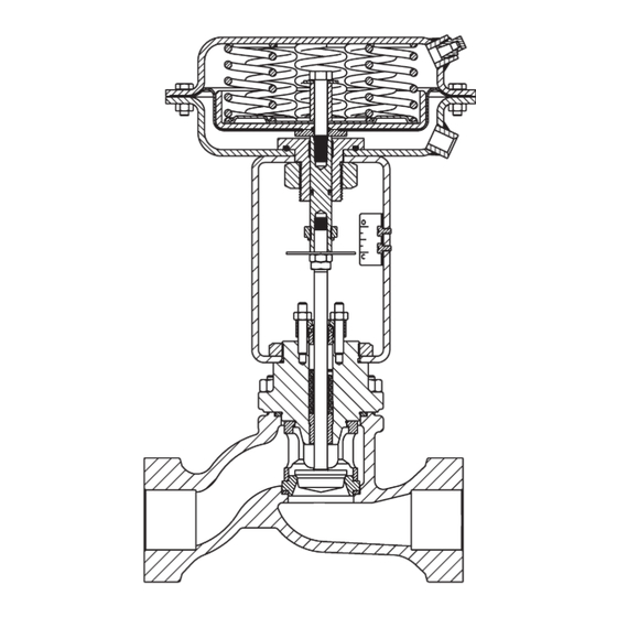
The Model 964 is a pneumatically actuated, sliding
stem globe-style control valve. Sizes are 1/2",3/4",
1", 1-1/2", & 2". Available in Cast Iron and Cast Steel
body ma te ri als.
Failure position is determined by actuator for:
"D" = Direct action; on increasing air loading pressure,
the actuator stem extends. Fail-safe position is with
the stem retracted.
"R" = Reverse action; on increasing air loading pressure,
the actuator stem retracts. Fail-safe position is with
the stem extended.
The valve is designed primarily for general service
or utility applications such as steam, air, oil, gas and
water.
II. REFERENCES
Refer to Technical Bulletin 964-TB for complete
tech ni cal specifications of a Model 964 coupled with
either Cashco Actuator Model C27 or C53.
www.cashco.com/techbulletins/964.pdf
Refer to following Installation, Operation &
Main te nance Manuals (IOM's) for either actuator
and/or devices that maybe mounted to a Model 964:
Actuators: www.cashco.com/iom/C27-C53.pdf
INSTALLATION, OPERATION, & MAINTENANCE MANUAL (IOM)
MODEL 964
GLOBE-STYLE
PNEUMATIC CONTROL VALVE UNIT
BODY IOM
SECTION l
SECTION II
Model 964
with ATO - FC Actuator
ABBREVIATIONS
ATC–FO – Air–to–Close, Fail Open
ATO–FC – Air–to–Open, Fail Close
CCW
– Counter Clockwise
CW
– Clockwise
D or DIR – Direct Acting
IAS
– Instrument Air Supply
LOAD
– Positioner Output Air Pressure
R or REV – Reverse Acting
SIG
– Output Signal from Instrument
V
– Vent
IOM-964
12-16
Advertisement

Subscribe to Our Youtube Channel
Related Manuals for cashco 964


Summary of Contents for cashco 964
- Page 1 II. REFERENCES ABBREVIATIONS Refer to Technical Bulletin 964-TB for complete ATC–FO – Air–to–Close, Fail Open tech ni cal specifications of a Model 964 coupled with ATO–FC – Air–to–Open, Fail Close either Cashco Actuator Model C27 or C53. – Counter Clockwise www.cashco.com/techbulletins/964.pdf...
-
Page 2: Installation
964, is ac cept able. If hydro test pressure exceeds the 1-1/2 x CWP limit, the 964 must be re moved for such testing. Before pres sur iza tion, the valve plug should be lifted from the seat if of ATO-FC action. - Page 3 DO NOT WALK AWAY AND LEAVE A MANUALLY CONTROLLED CONTROL VALVE UNATTENDED! 1. Ensure that the Model 964 unit has been prop er ly adjusted and cal i brat ed, in clud ing 8. Confirm that action of con trol ler and the po si tion er, if in stalled.
-
Page 4: Maintenance
All Item Num bers that are with respect to removed. If actuator has handwheel - see the body assembly (BA) of a Model 964 Actuator IOM for removal instructions. are not un der scored; i.e. (32). Reference with respect to the po si tion er is in double 2. - Page 5 (26) - over threaded end of plug/ stem (3). Con tin ue to lower the actuator assembly (AA) until there is ap prox i mate ly 1/4" (6 mm) space between the two stems (6) (3). IOM-964...
- Page 6 “out” of bonnet (2); press “in” new and seat ring (11) from the body (1) cavity. guide bushing (8). c. Reinstall bonnet (2) back through yoke 7. From the top works as sem bly, loosen the stem (3), and secure with yoke nut (29). IOM-964...
- Page 7 (2) until it ap pears through the top side. Place recorded per D. Step 9. bonnet on body. (NOTE: The cage for 2" 34. Rotate both jam nuts (18) up tight against size is integral with bonnet (2).) position in di ca ting washer (26). IOM-964...
- Page 8 (3, 6) length is too short. ses; i.e. ((AP)). All item numbers that are with a. Rotate both jam nuts (18) down to base of respect to this IOM-964 are not un der scored; threads on stem (3) and tighten together. i.e. (3).
- Page 9 (26) to the "C" mark on the in di ca tor plate upper actuator con nec tion. See Section IV. A. (23), mak ing sure to use the “top edge” of 6. for appropriate supply pressure. DO NOT LOAD with any air pressure at this point. IOM-964...
-
Page 10: Troubleshooting Guide
Change operation parameters to relieve causes of cavitation. Replace valve with valve equipped for cavi ta tional control. D. High outlet velocity. Re duce flow rate and/or pressure drop. Use multiple valves in series or parallel. Increase outlet pipe size. IOM-964... - Page 11 7. Body flange leakage. Possible Causes Remedies Over-tightening fl ange bolting. Loosen bolting, replace gasket, reinstall new flange bolting. Replace warped flang es. Improper pipe supports and anchors. Provide piping anchors and guides at control valve sta- tion. Restrain bending movements. IOM-964...
-
Page 12: Section Viii
Cashco, Inc. does not assume responsibility for the selection, use or maintenance of any product. Responsibility for proper selection, use and maintenance of any Cashco, Inc. - Page 13 1/2"–1-1/2" Sizes MODEL 964 Figure 3: Composition Seat Ar range ment IOM-964...
- Page 14 2" Size MODEL 964 Item No. De scrip tion Item No. De scrip tion Packing Flange Stud Body Packing Flange Nut Bonnet Studs - Body Plug & Stem Subassembly ‡ Stud Nuts Packing Flange Jam Nuts Packing Follower Packing Washer Packing ‡...
- Page 15 ATEX requires that all components and equipment be evaluated. Cashco pressure regulators are considered components. Based on the ATEX Directive, Cashco considers the location where the pressure regulators are installed to be classified Equipment-group II, Category 3 because flammable gases would only be present for a short period of time in the event of a leak.
- Page 16 If the above issues are addressed by selecting options that do not have potential sources of ignition, avoiding options that have not been assessed, and by taking the proper usage issue precautions, then Cashco regulators can be considered to be a mechanical device that does not have its own source of ignition and thus falls outside the scope of the ATEX directive.
Need help?
Do you have a question about the 964 and is the answer not in the manual?
Questions and answers