Table of Contents
Advertisement
Advertisement
Table of Contents

Related Manuals for Eaton MTL831B


Summary of Contents for Eaton MTL831B
-
Page 2: Table Of Contents
CONTENTS PAGE About this manual ........................1 Related documents ................................1 Product description ................................. 1 Getting started..........................1 Mechanical installation ....................... 1 Location ..................................1 Mounting options ................................1 CONNECTIONS ..........................3 RTD inputs ..................................3 THCs and mV inputs ............................... 5 Mixed inputs .................................. -
Page 3: About This Manual
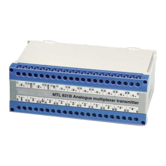
ENC83-SS - to provide suitable IP67 protection if the transmitter is located in an exposed area. The MTL831B can monitor up to 16 inputs from THC or millivolt sources or up to 15 inputs from 2, 3 or 4-wire RTDs. - Page 4 3.2.2 Mounting on a flat surface (figures 2 and 3) Turn the unit upside down. With a screwdriver, apply an anti-clockwise force against the retaining arm of one of the base clips to release it from its recess. Hold the arm in this position and slide the clip outwards. Release the retaining arm to engage the tooth in the base moulding.
-
Page 5: Connections
The user should be aware that any break in the excitation current a resistor equal in value to the resistance of the loop wiring used circuit will affect all of the RTDs connected to the MTL831B. to connect that RTD. The internal switch must then be set to 3-wire... - Page 6 4.1.2 4-wire RTDs (see figure 7) Connect a link wire between the +ve source lead of each RTD (except the last) and the –ve source lead of the next RTD. Wiring 4-wire RTDs requires additional terminal blocks. The ENC83 and ENC83-SS enclosures provide such terminals, as well as earth Connect the –ve source lead of the first RTD to the –ve end of the terminals for all cable screens.
-
Page 7: Thcs And Mv Inputs
Highway connections Data highway 1OOR The data highway connections H1 (1,2) and H2 (4,5) are also the source of d.c. power for the MTL831B. The user may choose either, or both to provide redundancy. 4.4.1 Transmission distances The highway length will depend upon two key factors: the type and... -
Page 8: Mtl3052 Digital Isolator
0ne or both Multi-transmitter connections 1OO R highways to receiver can be Connect the highway(s) to a receiver for one MTL831B transmitter as used in (e). (figure 12) Highway1 to Connect one or two data highways between output terminal pairs H1... -
Page 9: Cable Screens
Cable screens Transmitter Address Screens of sensor cables should be earthed at the MTL831B. If a Four addresses (1 to 4) are possible with the SW100 switch settings sensor cable is earthed at the sensor, then it should not be earthed or as shown in Figure 13. -
Page 10: Atex Information
EN 60079-0 and EN60079-11. The If the outer enclosure of the apparatus needs to be cleaned, this MTL831B transmitter is certified ‘ia’ and is normally mounted in should be done with a cloth lightly moistened by a dilute mixture a Zone 1 hazardous area. - Page 11 INM831B Rev 4...
Need help?
Do you have a question about the MTL831B and is the answer not in the manual?
Questions and answers