Table of Contents
Advertisement
Quick Links
M100 Stopswitch
STOPPED MOTION MONITOR
WARNING:
AVERTISSEMENT:
Do not use the M100 Stopswitch for belt slip applications!
N'utilisez pas l'interrupteur d'arrêt M100 pour les applications
de glissement de courroie !
INSTALLATION INSTRUCTIONS
OPERATION MANUAL
Part No. M1001V10F
www.go4b.com/usa
®
C
US
APPROVED
Class II Div. 1
Advertisement
Table of Contents

Related Manuals for 4B M1001V10F


Summary of Contents for 4B M1001V10F
- Page 1 STOPPED MOTION MONITOR ® APPROVED Class II Div. 1 WARNING: AVERTISSEMENT: Do not use the M100 Stopswitch for belt slip applications! N’utilisez pas l’interrupteur d’arrêt M100 pour les applications de glissement de courroie ! INSTALLATION INSTRUCTIONS OPERATION MANUAL Part No. M1001V10F www.go4b.com/usa...
-
Page 3: Table Of Contents
TABLE OF CONTENTS CUSTOMER SAFETY RESPONSIBILITIES Page 4 - 5 PRODUCT OVERVIEW Page 6 SPECIFICATIONS Page 6 DIMENSIONS Page 7 INSTALLATION Page 7 STANDARD WIRING DIAGRAM Page 8 TESTING & COMMISSIONING Page 9 TROUBLESHOOTING GUIDE Page 10 PARTS & ACCESSORIES Page 10 PRODUCT WARRANTY Page 11... -
Page 4: Customer Safety Responsibilities
Please read the safety precautions carefully before operating the product. With each product you purchase from 4B, there are some basic but important safety considerations you must follow to be sure your purchase is permitted to perform its design function and operate properly and safely, giving you many years of reliable service. - Page 5 Correct installation of the product is important for safety and performance. If you have not asked 4B to perform the installation of the unit on your behalf, it is critical for the safety of your operation and those who may perform work on your operation that you select a qualified and competent electrical installer to undertake the installation.
-
Page 6: Product Overview
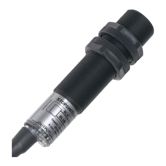
WARNING AVERTISSEMENT • Rotating machinery can cause serious injury or death • Always lockout and tagout the machine prior to installation • Les machines en rotation peuvent provoquer des blessures graves, voire la mort. • Toujours verrouiller et étiqueter la machine avant l’installation PRODUCT OVERVIEW The M100 Stopswitch is a simple inductive proximity shaft speed monitoring device. -
Page 7: Dimensions
2 x 20 AWG Conductors INSTALLATION Fasten the M100 Stopswitch to a suitable mounting bracket with guard, such as 4B’s Whirligig® universal shaft sensor mount, with the nose of the switch within the sensing range of the target, as shown below - Ferrous Target - 5/16 in. -
Page 8: Standard Wiring Diagram
NOTE 18 mm to 1/2 inch NPT Conduit Adapter Available (Part # A12NPT) STANDARD WIRING DIAGRAM All wiring must be In accordance with local and national electrical codes and should be undertaken by an experienced and qualified electrician. All wiring methods must be suitable for ClassII Division1 (Groups E,F&G) Hazardous Locations. -
Page 9: Testing & Commissioning
TYPICAL CONTROL WIRING START STOP Blue Black The relay is held in during normal operation. If the shaft stops rotating, the relay will drop M100 out and the motor will shutdown. TESTING AND COMMISSIONING 1. Check that the unit is correctly installed (see standard wiring diagram). 2. -
Page 10: Troubleshooting Guide
200 mA. Slide a screwdriver blade across the Red LED (input) does face of the sensor, the input LED should flicker. If not, contact 4B. not Illuminate If the input LED does flicker, move the front face of the sensor closer to the target and check the target size as specified under “INSTALLATION”. - Page 11 DEFECTS IN WORKMANSHIP OR MATERIALS UNDER NORMAL USE FOR ONE (1) YEAR AFTER DATE OF PURCHASE FROM 4B. ANY PRODUCT DETERMINED BY 4B AT ITS SOLE DISCRETION TO BE DEFECTIVE IN MATERIAL OR WORKMANSHIP AND RETURNED TO A 4B BRANCH OR AUTHORIZED SERVICE LOCATION, AS 4B DESIGNATES, SHIPPING COSTS PREPAID, WILL BE, AS THE EXCLUSIVE REMEDY, REPAIRED OR REPLACED AT 4B’S OPTION.
- Page 12 Tel: +33 3 2442 3226 Tel: +27 11 708 6114 Tel: +61 7 3216 9365 Changzhou 213164, Jiangsu Province, Fax: +27 11 708 1654 Fax: +61 7 3219 5837 China Tel: +86 519-88556006 www.go4b.com Copyright © 2015 4B Group - All Rights Reserved REV030624...
Need help?
Do you have a question about the M1001V10F and is the answer not in the manual?
Questions and answers