Table of Contents
Advertisement
WIRELESS MICROPHONES SYSTEM
CONTENTS
Thank you for purchasing TOA's TRANTEC S5 series Wireless Microphone system.
Please carefully follow the instructions in this manual to ensure long, trouble-free use of your equipment.
OPERATING INSTRUCTIONS
S5.5 series
8.
9.
Advertisement
Table of Contents

Related Manuals for Trantec S5.5 series


Summary of Contents for Trantec S5.5 series
-
Page 1: Table Of Contents
6. RECEIVER FREQUENCY SELECTION 14. TROUBLESHOOTING 7. MISCELLANEOUS SETTINGS ON 15. CERTIFICATIONS RECEIVER 16. SPECIFICATIONS Thank you for purchasing TOA's TRANTEC S5 series Wireless Microphone system. Please carefully follow the instructions in this manual to ensure long, trouble-free use of your equipment. -
Page 2: Safety Precautions
1. SAFETY PRECAUTIONS • Be sure to read the instructions in this section carefully before use. • Make sure to observe the instructions in this manual as the conventions of safety symbols and messages regarded as very important precautions are included. •... - Page 3 • When moving the unit, be sure to remove its power supply cord from the wall outlet. Moving the unit with the power cord connected to the outlet may cause damage to the power cord, resulting in fire or electric shock. When removing the power cord, be sure to hold its plug to pull.
-
Page 4: General Description
2. GENERAL DESCRIPTION The TOA’s TRANTEC S5 series W i r e l e s s M i c r o p h o n e s y s t e m is designed for use on the UHF f r e q u e n c y band, and suitable for vocal or speech reinforcement applications. It features a compander circuit which minimizes the influence of ambient noise. -
Page 5: Nomenclature And Functions
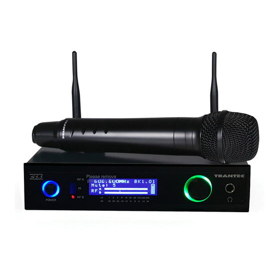
5. NOMENCLATURE AND FUNCTIONS Receiver : S5.5-RXA [Front] Mute : 5 MUTE 1. Power switch 5. LCD screen Press this switch to turn the power on, and press it Displays the receiving status when the unit is in again to turn off the power. normal operating state. - Page 6 [Rear] 9. USB port 12. AF output Used to connect the unit to a PC with the Unbalanced 1/4” jack socket, male type installed software. +9 dBm (maximum) 10. Cable hanger 13. AF output level selector Hook the power cable onto this part. Sets the output level from the AF outputs by selecting either MIC or LINE 14.
- Page 7 Handheld microphone : S5.5-HDX2 & S5.5-HCX2 1. Power switch 5. Muting switch Slide this switch towards “ON” position to Flick this switch towards the power lamp to turn the power on, and slide it again towards mute the audio. “OFF” position to turn off the power. 6.
- Page 8 Belt-pack transmitter : S5.5-BTX2 1. Power lamp 6. Up down key [▲▼] A blue LED lights with turning on the power Used to select the channel (frequency) and AF switch. gain. (The frequency must be identical to that of receiver.). 2.
-
Page 9: Receiver Frequency Selection
Note In the case of the S5.5 it will be added to the Custom USER bank. You can download USER banks via the TRANTEC software. Please refer to the software manual on this CD for more information. - Page 10 6-3. To Program a transmitter with Bank information via receiver Infrared port Step 1. Press and hold the “Jog-wheel” for approximately 3 seconds if the receiver is not in mute to enter the MAIN MENU. You will enter the MAIN MENU immediately if the receiver is in mute.
-
Page 11: Miscellaneous Settings On Receiver
7. M ISCELL ANEOUS SETTINGS ON RECEIVER 7-1. Mute/Squelch Settings The S5 series uses sophisticated internal mute functions including Pilot Tone, Noise and RSSI to prevent noise break through from external sources when the transmitter is in the “OFF” position. The RSSI (Received signal strength) portion is user adjustable via the RX SETTINGS menu. - Page 12 7-4. Channel Scan The scanning feature can determine which frequencies are currently being used in the vicinity of your receiver. Step 1. From the main screen press the “Jog- Wheel” to go to MAIN MENU, rotate till FREQ SEL, is underlined and push.
-
Page 13: Handheld Microphone Set-Up
7-7. LCD Contrast Step 1. Push the “Jog-Wheel” to bring up the MAIN MENU. Rotate the “Jog-Wheel” to underline RX SET and push. Step 2. Rotate to underline LCD and push, then rotate the “Jog-Wheel” to alter the LCD CONTRAST. Step 3. -
Page 14: Beltpack Transmitter Set-Up
Step 7. M u t e s w i t c h Incorporated in the handheld end cap is a Power On LED and Audio Mute switch. To mute the audio, flick the switch towards the LED. Mute Power Turn on Audio Mute swithch, Power On LED blinks. switch lamp Turn on Power Switch with audio muting, after... -
Page 15: S5 Series Rack Mount Kit
11. S5 Series Rack Mount Kit 11-1. 19” Rack Mounting for 2 x S5 Series Receivers The rack mounting kit is supplied as standard with S5.5 systems. Step 1. Unscrew the front 3 lid retaining screws from opposite sides of each receiver case and fit the angled rack brackets, using the supplied screws. - Page 16 11-2. 19” Rack 1 x S5 Series Receiver with Front Mount Antenna The rack mounting kit is supplied as standard with S5.5 systems. Step 1. Unscrew 3 x lid retaining screws (M3x6) from the front left side of the chassis (viewed from the front) and fit the small angled rack bracket, using the supplied screws.
-
Page 17: Mini-Xlr Wiring Connections
12. Mini-XLR Wiring Connections Beltpack Audio Mini-XLR Connections 1. Ground 2. Bias 5 V 3. AF Hi-Z 4. AF Load Resistor Solder connections for Mini-XLR flying socket 12-1. Wiring for Mini-XLR Flying Socket 2 Wire Mic Pin 1: Ground Pin 2: 5 V Pin 3: AF Pin 4: Internal AF load resistor Link pins 3 and 4 and add a 10 KΩ... -
Page 18: Operational Hints
13. OPERATIONAL HINTS • When the transmitter user moves in a facility, signal dropouts (momentary losses of signal reception) may be encountered. These dropouts are caused by the building's architectural designs or materials which block the travel of or reflect the radio signal. If this occurs, the user needs to change locations for better signal reception. -
Page 19: Certifications
Poor range or sound dropouts Receiver Reception lamps [A The system must be set up and B] are flicking or RF signal within recommended range. level meter turn light off.. The transmitter must be used in line of sight from the receiver. Check the channel scan, confirm nearby source of interference, and change the receiver and the... -
Page 20: Specifications
>110 dB(A) Operating Temperature Range -10°C to +50° C TRANSMITTER S5.5-HDX2, S5.5-HCX2 S5.5-BTX2 Dynamic with cardioid pattern (HDX) TRANTEC series lavalier and head set Microphone unit Electret condenser with cardioid pattern microphone (HCX) RF Carrier Power 10 mW 10 mW...
Need help?
Do you have a question about the S5.5 series and is the answer not in the manual?
Questions and answers