
Related Manuals for Sicor SGS6


Summary of Contents for Sicor SGS6
- Page 1 OPERATION AND MAINTENANCE MANUAL SGS6 COD.: MUM0126 REV. 05 SICOR S.p.A. Head Office and Production Centre Viale Caproni 32 (Industrial Area) 38068 Rovereto (TN) Italy Copy of the original file MUM0126_REV05 Italian...
-
Page 2: Table Of Contents
SGS6 INDEX LETTER TO THE CUSTOMER ....................2 DESCRIPTION OF THE GEARLESS MACHINE ..............2 2.1. DIMENSIONS/TECHNICAL SPECIFICATIONS SGS6 ............3 MACHINE IDENTIFICATION ....................4 WARRANTY ........................5 GENERAL DELIVERY NOTES ....................6 SAFETY PRECAUTIONS .......................7 SAFETY REQUIREMENTS ....................8 MOVING THE WINCH ......................10 NOTES FOR INSTALLATION ....................12 9.1. -
Page 3: Letter To The Customer
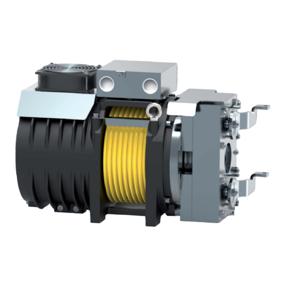
SGS6 LETTER TO THE CUSTOMER Dear Customer, SICOR gearless machines are designed and manufactured in accordance with the Machinery machine was delivered; that this manual has been delivered with the machine and that the DESCRIPTION OF THE GEARLESS MACHINE for the handling of cable elevator systems. -
Page 4: Dimensions/Technical Specifications Sgs6
SGS6 2.1. DIMENSIONS/TECHNICAL SPECIFICATIONS SGS6 Ø D1 Max Weight System S3 40% Load Power** [mm] [kg] [kgm²] [Nm] [kW] 0,07 0,08 0,12 0,15 Standard Encoder Data 2x180 [Nm] Heidenhain [V DC] Model ECN 1313 [V DC] 13 bits Power 2x68... -
Page 5: Machine Identification
SGS6 MACHINE IDENTIFICATION... -
Page 6: Warranty
SGS6 WARRANTY • recognised as faulty. Labour, travel and board and lodging costs must be met by the Customer. • • gaskets, revolving bearings. • • Customer under warranty or will send its own technicians. -
Page 7: General Delivery Notes
SGS6 GENERAL DELIVERY NOTES there is no visible damage to the gearless machine or its accessories Machine data sheet Work Order... -
Page 8: Safety Precautions
SGS6 SAFETY PRECAUTIONS WHEN THESE WARNINGS APPEAR, PROCEED WITH THE UTMOST CAUTION. -
Page 9: Safety Requirements
SGS6 SAFETY REQUIREMENTS Before installing the gearless machine the customer must verify that the concrete slab and/or the factors. LIFTING EXCLUSION OF POWER SOURCES WARNING Do not lean and/or sit on the gearless machine, either when it is in or out of service. - Page 10 SGS6 MALFUNCTIONS.
-
Page 11: Moving The Winch
SGS6 MOVING THE WINCH WARNING RISK OF CRUSHING, IMPACT AND ABRASION WARNING CAUTION • lay the crate on the ground slowly • •... - Page 12 SGS6 CAUTION machine.
-
Page 13: Notes For Installation
MECHANICAL INSTALLATION WARNING For other values, consult SICOR. The customer must make sure that the electrical system has suitably gauged cables, is correctly Allow a minimum of 80 mm between the encoder and the wall so that it is always accessible... -
Page 14: Cable Installation
SGS6 9.1.1. CABLE INSTALLATION in any way. 9.1.2. SECURING THE GEARLESS MACHINE screws is 70 Nm. 9.1.3. CABLE GUARD... -
Page 15: Electrical Installation
SGS6 9.2. ELECTRICAL INSTALLATION 9.2.1. ELECTRIC MOTOR DO NOT CONNECT THE MACHINE DIRECTLY TO THE POWER GRID. THE POWER MUST BE SUPPLIED BY A SUITABLE ELECTRONIC CONVERTER. IMPORTANT NOTE Thermistors The thermistors MUST ONLY BE CONNECTED TO A SPECIFIC DEVICE. -
Page 16: Terminal Board Wiring Diagram
SGS6 9.2.2. TERMINAL BOARD WIRING DIAGRAM Thermistors L1 L2 L3 terminals of the thermistor... -
Page 17: Encoder
SGS6 9.3. ENCODER • Absolute rotary encoder with EnDat interface; • Rotary encoder with Sin/Cos interface;... - Page 18 SGS6 9.3.1. connected or disconnected. 6/10/15/20/25 m inverter side connector. • 6/10/15/20/25 m C1 MINITEK 12 PIN WIRE COLOUR SIGNAL Brown Green CLOCK Violet White Red/Blue Grey DATE Pink Grey/Pink Blue Sensor 0 V Black Yellow Sensor 5 V...
- Page 19 SGS6 CABLE LENGTH MORE THAN 25 METRES connected or disconnected. extensions over 25 m 0.3m • CABLE LENGTH OF MORE THAN 25 METRES C2 17 PIN WIRE COLOUR SIGNAL Blue White Brown/Green Violet CLOCK Yellow White/Green Blue/Black Red/Black Grey DATE...
-
Page 20: Rotary Encoder Sin/Cos Interface Configuration
SGS6 9.3.2. ROTARY ENCODER SIN/COS INTERFACE CONFIGURATION extension cables is necessary in order to connect this encoder to the inverter. Please refer to the table below to connect the encoder to the inverter. connected or disconnected. 6/10/15/20/25 m inverter side connector. -
Page 21: Instructions For Installing The Extension Cable On The Heidenhain Endat Ecn 1313 Encoder
SGS6 9.3.3. INSTRUCTIONS FOR INSTALLING THE EXTENSION CABLE ON THE HEIDENHAIN ENDAT ECN 1313 ENCODER of the encoder • • •... - Page 22 SGS6 • Bushing Bushing • The removal of the extension cable is not recommended, if this is unavoidable carry out the...
-
Page 23: Electromagnetic Brake
SGS6 9.4. ELECTROMAGNETIC BRAKE be controlled. The two brake circuits MUST be monitored manual. descent of the elevator. -
Page 24: Emc Directive
SGS6 IMPORTANT NOTES between 10mA min. and 50 mA max. at 24V DC. DO NOT use detergents containing solvents and/or oily 9.4.1. EMC DIRECTIVE... -
Page 25: Manual Brake Release Lever Remote Control Kit
SGS6 9.4.2. MANUAL BRAKE RELEASE LEVER REMOTE CONTROL KIT device of 2.5 m or 5 m in length. • • • lever; • •... - Page 26 SGS6 Manual emergency manoeuvre is a dangerous task. It can be used to move the cab involved.
-
Page 27: Manual Brake Release Lever Extension Kit
SGS6 9.4.3. MANUAL BRAKE RELEASE LEVER EXTENSION KIT device • Always remove the manual release levers ~ 400 mm Manual emergency manoeuvre is a dangerous task. It can be used to move the cab excluding... -
Page 28: Power Supply Unit
SGS6 9.5. POWER SUPPLY UNIT [VAC] [VDC] bridge FF315A Terminals... -
Page 29: Power Supply Unit Electrical Connection Drawings
SGS6 9.5.1. POWER SUPPLY UNIT ELECTRICAL CONNECTION DRAWINGS max. 250V~ 2,5A - 1/025.000.6 [U- =0,9xU~] Full-wave rectifier Bridge max. 250V~ 2,5A - 1/025.000.6 [U- =0,9xU~] Full-wave rectifier Bridge... - Page 30 SGS6 max. 250V~ 2,5A - 1/025.000.6 [U- =0,9xU~] Full-wave rectifier...
-
Page 31: Starting The Gearless Machine For The First Time
SGS6 STARTING THE GEARLESS MACHINE FOR THE FIRST TIME data. CAUTION WARNING etc...). by the EN 81.1 standard. The system can now be handled. -
Page 32: Maintenance
SGS6 MAINTENANCE of this manual. CAUTION gloves, safety shoes). materials WARNING The gearless machine MUST NEVER BE OPENED. -
Page 33: Encoder Replacement
SGS6 11.1. ENCODER REPLACEMENT Loosen the screw on the outer ring with an Allen key Remove the cover on the rear Remove the M10 screw; Remove the encoder Figure 1... -
Page 34: Ventilation Kit
SGS6 Remove the cover on the rear of the encoder Place the encoder inside the housing, taking care to centre the cone of 1.25 Nm THE HEIDENHAIN ENDAT ECN 1313 ENCODER) and close the cover with the Allen wrench SW3/ PROCEDURE). -
Page 35: Emergency Operation
SGS6 EMERGENCY OPERATION gearless machine. IN THIS CONDITION THE CABIN WILL MOVE DOWNWARD OR UPWARD DEPENDING ON THE LOAD AND/OR BALANCE CONDITIONS OF THE SYSTEM. WARNING WHEN THE MOTOR IS NOT POWERED, IT IS UNABLE TO GENERATE TORQUE. IN THIS SITUATION, IF THE BRAKE IS OPENED THE CABIN CAN ACCELERATE IN AN UNCONTROLLED MANNER. - Page 36 SICOR S.p.A. Head Office and Production Centre Viale Caproni 32 (Industrial Area) 38068 Rovereto (TN) Italy...
Need help?
Do you have a question about the SGS6 and is the answer not in the manual?
Questions and answers