Advertisement
Quick Links
Download this manual
See also:
Owner's Manual
Owner'sManual
with Installation Instructions
Banks
Derringer
®
Tuner
2011-2017 F-150 3.5L EcoBoost
2015-2017 F-150 2.7L EcoBoost
USE WITH SYSTEM P/N 66545, 66546, 66547
Advertisement

Summary of Contents for banks Derringer
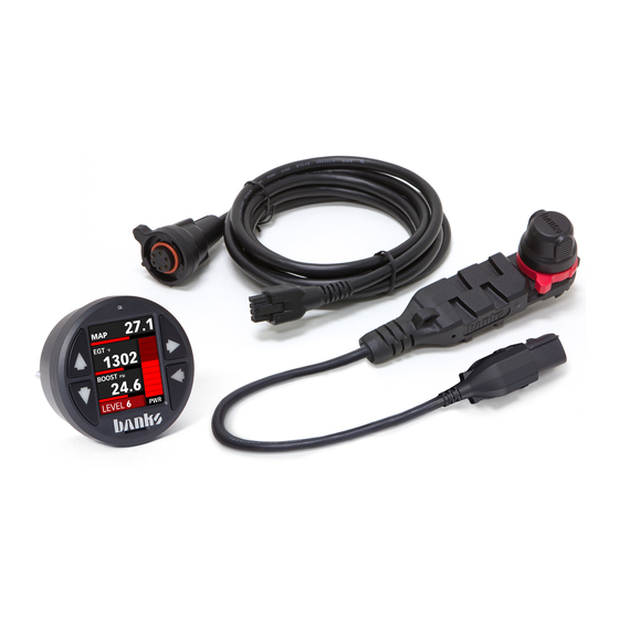
- Page 1 Owner’sManual with Installation Instructions Banks Derringer ® Tuner 2011-2017 F-150 3.5L EcoBoost 2015-2017 F-150 2.7L EcoBoost USE WITH SYSTEM P/N 66545, 66546, 66547...
-
Page 2: General Installation Practices
General Installation Practices CAUTION! Do not use floor jacks Before starting work, familiarize to support the vehicle while yourself with the installation procedure working under it. Do not raise by reading all of the instructions. the vehicle onto concrete blocks, The exploded views provides only masonry or any other item not general guidance. - Page 3 Ram-Air's lifetime filter has a huge outlet Monitor and control what’s happening with deep filter pleats that maximize flow under the hood with a Banks man-machine and a complete air filter housing that draws interface. Read and clear trouble codes, set...
- Page 4 Wiring Diagram: Stand Alone Tuner Configuration...
- Page 6 Wiring Diagram: iDash 1.8" Configuration...
- Page 8 Section 1 INSTALLATION OF WIRING HARNESS, CONNECTIONS & DERRINGER the intake. Disconnect the MAP sensor Use 10mm wrench to disconnect plug, pushing down on the release the battery ground cable from the lever until it releases, then pulling battery (If equipped with more than...
- Page 9 Figure 4 Figure 5...
- Page 10 Then over to the side of the the wire harness gasket. Then feed engine bay on the driver’s side fender. the 6-pin end of the Derringer starter Take care to route the harness over cable through the hole. Plug the round...
- Page 11 Figure 7 Figure 8...
- Page 12 Figure 9 Plug the OBDII cable into the OBDII port under the dash (Figure 10). NOTE: If using the Switch configuration, perform steps 9-11. If using iDash 1.8" Gauge configuration, skip to step 12. Plug the 4-pin connector from the OBDII cable, the 6-pin connector from the starter cable, and the 2-pin connector from the switch cable into the Y-harness (Figure 11).
- Page 13 Figure 10 Figure 11...
- Page 14 Install the black terminal cap onto Figure 12 the Derringer in place of the grey cap when using the Derringer in iDash 1.8" gauge configuration (Figure 14). Secure the harness connectors under the dash, avoiding any moving parts, with supplied Zip ties.
- Page 15 Figure 13 Figure 14...
-
Page 16: Troubleshooting
OPERATION OF THE DERRINGER MODULE Setting Desired Power Level: Your Derringer tuner module has three settings. These are Sport, Plus, and Stock (off). You can set the desired power level while the engine is running, under power or off. It is recommended that you do not switch modes under high throttle applications. - Page 17 Code Event Course of Action Turn ignition OFF and check the male and female TIP sensor connectors. Turn ignition back ON and Throttle Inlet Pressure (TIP) re-check for presence of code. If code does not Input Voltage re-appear at key ON, start engine and check for Out of Range.
- Page 18 Section 4 PLACEMENT OF THE BANKS POWER DECALS Banks provides the best performance chips and programmers.


Need help?
Do you have a question about the Derringer and is the answer not in the manual?
Questions and answers