Table of Contents
Advertisement
Owner'sManual
with Installation Instructions
Banks
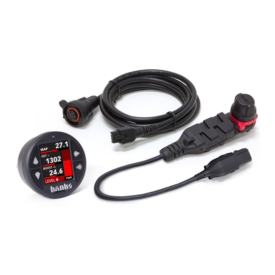
Derringer
®
Tuner
All Derringer Applications
THIS MANUAL IS FOR USE WITH SYSTEM P/N:
66575, 66545, 66577, 66547, 66571, 66541, 66572, 66582, 66552
Gale Banks Engineering
546 Duggan Avenue • Azusa, CA 91702
(626) 969-9600 • Fax (626) 334-1743
Product Information & Sales: (888) 635-4565
Customer Support: (888) 839-5600
Installation Support: (888) 839-2700
bankspower.com
©2018 Gale Banks Engineering
8/06/2018 PN 97671 v.1.1
Advertisement
Table of Contents
Troubleshooting

Subscribe to Our Youtube Channel
Related Manuals for banks Derringer


Summary of Contents for banks Derringer
- Page 1 Installation Instructions Banks Derringer ® Tuner All Derringer Applications THIS MANUAL IS FOR USE WITH SYSTEM P/N: 66575, 66545, 66577, 66547, 66571, 66541, 66572, 66582, 66552 Gale Banks Engineering 546 Duggan Avenue • Azusa, CA 91702 (626) 969-9600 • Fax (626) 334-1743 Product Information &...
- Page 2 If you have any questions working under it. Do not raise concerning the installation the vehicle onto concrete blocks, of your Banks Techni-Cooler, masonry or any other item not please call our Technical Ser- intended specifically for this use. vice Hotline at (888) 839-2700...
- Page 3 Disclaimer of Liability The BUYER is responsible to obey all applicable federal, state, and Gale Banks Engineering Inc., and its local laws, statutes, and ordinances distributors, employees, and dealers when operating his/her vehicle, and (hereafter “SELLER”) shall in no way the BUYER agrees to hold SELLER be responsible for the product’s proper...
- Page 4 Disclaimers, cont'd... Limitation of Warranty and understands this agreement and accepts its terms and conditions. Gale Banks Engineering Inc. (hereafter “SELLER”), gives Limited Warranty as to description, quality, merchantability, fitness for any particular purpose, productiveness, or any other matter of SELLER’s product sold herewith.
-
Page 5: Table Of Contents
Table of Contents 1. Installation of Wire Harness and Derringer Tuner ......7 1.1 Derringer Tuner System Configuration ............8 1.1.1 Stand Alone/Switch Configuration ............8 1.1.2 iDash 1.8 Configuration ................10 1.2 Derringer Sensor Harness Installation ............12 1.3 Derringer Tuner Installation ................14 1.4 Vehicle Specific Instructions ...............21 1.4.1 2011-2016 F150 EcoBoost ..............22... - Page 6 This page is left blank purposely... 97671 v.1.1...
-
Page 7: Installation Of Wire Harness And Derringer Tuner
SECTION 1 Installation of Wire Harness and Derringer Tuner 97671 v.1.1... -
Page 8: Derringer Tuner System Configuration
SECTION 1.1 DERRINGER TUNER SYSTEM CONFIGURATION 1.1.1: Stand Alone/Switch Config. Bypass Plug (Optional) *Varies based on application Application Specific Harness 97671 v.1.1... - Page 9 (Ex: MAP, FRP, TIP, MAF,EGT..etc) 97671 v.1.1...
-
Page 10: Idash 1.8 Configuration
SECTION 1.1 DERRINGER TUNER SYSTEM CONFIGURATION 1.1.2: iDash 1.8 Config. Bypass Plug (Optional) *Varies based on application Application Specific Harness 97671 v.1.1... - Page 11 NOTICE: Only use one In-Cab Term. for iDash 1.8 Hardware Rev 1 Terminator Jumper Jumper Block for iDash 1.8 Hardware Rev 2 (HW Rev 2 only) (Ex: MAP, FRP, TIP, MAF,EGT..etc) 97671 v.1.1...
-
Page 12: Derringer Sensor Harness Installation
Section 1.2 DERRINGER SENSOR HARNESS INSTALLATION NOTE: The following procedure Figure 1.2-3 and images are for demonstration purposes only. Please refer to section "1.4 Vehicle Specific Instructions" of the manual for further guidance on locating sensor, routing and mounting Derringer application specific harness. - Page 13 Section 1.2 DERRINGER SENSOR HARNESS INSTALLATION, cont'd... Disconnect the OEM harness from Route the Derringer harness along the sensor. suitable path. It is recommended to route the Derringer harness along an existing OEM harness path. See NOTE: Section 1.4 for further assistance in...
-
Page 14: Derringer Tuner Installation
Derringer application specific harness. However, installation process should be similar. Connect the Derringer module to Figure 1.3-3 the Derringer harness and mount it in a secure location with provided zip tie. See Figures 1.3-1 Figure 1.3-1 Plug the round connector end of the... - Page 15 Terminator install gray dust cap and if using iDash Cap at all times. Configuration install black terminator cap to the other side of the Derringer module. See Figures 1.3-6. Secure it by rotating locking ring clockwise. See Figures 1.3-4 1.3-5.
- Page 16 Section 1.3 DERRINGER TUNER INSTALLATION, cont'd... Plug the OBDII cable into the OBDII Figure 1.3-7 port under the dash. See Figures 1.3-7 For Switch Configuration: NOTE: If using the Switch configuration, perform steps 6-8. If using iDash 1.8” Gauge configuration, skip to step 9.
- Page 17 Section 1.3 DERRINGER TUNER INSTALLATION, cont'd... For iDash Configuration: In-Cab Terminator. See Figures 1.3-12, Step 2A. NOTE: Only perform steps 9-11 if B. Connect the In-Cab Terminator to the using iDash gauge configuration. If iDash 6-Pin Port. See Figures 1.3-12., using the switch configuration skip Step 2B.
- Page 18 Section 1.3 DERRINGER TUNER INSTALLATION, cont'd... If you ONLY have HW Rev 2 iDash If using multiple iDash Gauges: 1.8’s: If you ONLY have HW Rev 1 iDash A. Connect the Y-Cable to the 6-pin 1.8’s: port of the first and second iDash 1.8 A.
- Page 19 Rev 1 or Rev 2, but only use a single ed, and connections are correct and terminator. tight. Make sure that the Derringer wire harness is not lying in the way of the brake and gas pedals, or any moving parts.
- Page 20 This page is left blank purposely... 97671 v.1.1...
-
Page 21: Vehicle Specific Instructions
SECTION 1.4 Vehicle Specific Instructions 97671 v.1.1... -
Page 22: 2011-2016 F150 Ecoboost
Manifold Absolute wire harness grommet. Then feed the Pressure (MAP) sensor at the back of the 6-pin end of the Derringer starter cable intake. Disconnect the MAP sensor plug, through the hole. Apply a little black... - Page 23 ROUTING LOCATION OF RECOMMENDED DERRINGER MOUNTING LOCATION (MOUNTED TO THE FENDER LIP) LOCATION OF Figure 1.4-2 Figure 1.4-3 MAP SENSOR MAP SENSOR CONNECTION CONNECTION Figure 1.4-4 Figure 1.4-5 NEW DERRINGER NEW DERRINGER CABLE ADDITION CABLE ADDITION LOCATION LOCATION 97671 v.1.1...
-
Page 24: 2017-2018 Gm 6.6 L5P
Connect the Derringer module to the Derringer sensor harness. NOTE: Locate a place to secure the Derringer GM L5P Derringer harness module near or along the fender, then connects to FRP and TMAP sensors. Pull zip-tie it in place. - Page 25 SECTION 1.4 VEHICLE SPECIFIC INSTRUCTION, cont'd... 1.4.2: 2017-2018 GM 6.6L L5P Figure 1.4-7 LOCATION OF TMAP LOCATION OF RECOMMENDED HARNESS ROUTE OEM HARNESS RECOMMENDED DERRINGER CONNECTORS MOUNTING LOCATION LOCKING TAB TMAP SENSOR (4 PIN) Figure 1.4-9 Figure 1.4-8 OEM HARNESS FRP CONNECTION...
- Page 26 Unclip the left side first. Firewall Cable Instruction See Figure 1.4-11 & 1.4-12. Locate the wire harness grommet and route the Derringer Starter Cable Fig. 1.4-12 through the firewall. To do this insert a large phillips screw driver to move the grommet edge aside.
-
Page 27: 2014-2017 Ecodiesel Ram/Jeep
Front of truck Wedge Lock must fully engage locking latch on factory harness. NOTE: EcoDiesel Ram and Jeep Derringer harness connects to FRP and MAP sensors (EGT Sensor Optional). Pull only on the connector, do not pull on the wires. Fig.1.4-17... - Page 28 (near turbo). The FRP sensor is located at the end of the fuel rail, close to the mentioned TMAP sensor. See Figure 1.4-18. Figure 1.4-18 LOCATION OF RECOMMENDED HARNESS ROUTE LOCATION OF TMAP RECOMMENDED DERRINGER MOUNTING LOCATION Figure 1.4-19 Figure 1.4-20 97671 v.1.1...
- Page 29 (Derringer Harness) must be oriented on same side as connector locking Connect the MALE ends of both latch and yellow lock (OEM Engine the FRP and TMAP Derringer harness Harness). to the sensors on-engine. Pay specific attention to the connector latch...
- Page 30 Derringer harness, and zip tie the oriented properly and latch securely branch in a safe location. See Figure when connected. Slide the factory 1.4-22.
- Page 31 EGT that runs along the driver side of the Connection. transmission. See Figure 1.4-24. Route the EGT branch of the Derringer Trace the EGT sensor connector branch harness along the driver side firewall. of the harness. (Thinner branch at the Ensure the harness is away from harness split) See Figure 1.4-25.
- Page 32 1.4.3: 2014-2017 ECODIESEL RAM/JEEP Fig. 1.4-26 Connect the female factory EGT connector to the male connector on the Derringer harness and the male factory connector to the female connector on the Derringer harness. Ensure that the connector locks are fully engaged. Confirm the connections are secure by tugging firmly on both sides of the connection.
- Page 33 Then carefully Derringer Starter Cable through the pull the remaining free length of the EOM grommet (behind the brake Derringer Starter Cable through the pedal) from the engine-side of the firewall.
-
Page 34: Derringer Tuner Operations
SECTION 2 Derringer Tuner Operations 97671 v.1.1... - Page 35 (switch down/away from slot) iDash 1.8 configuration: The plus calibration is designed for use When the Derringer is connected to an in everyday driving. This power level iDash 1.8, there are a total of 6 power adds a noticeable punch under high levels (level 6, 5, 4, 3, 2 and stock).
- Page 36 “Derringer” layout, the vertical bar graph on the right hand side represents, in real-time, how much power the Derringer is adding (See Figure 2-2). In Stock Mode there will be no change to the bar graph and in Sport Mode/Level 6 the bar graph will reach 100% under proper operating conditions.
-
Page 37: Troubleshooting
SECTION 3 Troubleshooting 97671 v.1.1... -
Page 38: General Troubleshooting Info
LED flashes green for the second digit. After the diagnostic code is displayed, additional codes will be displayed in sequence, separated by 4 seconds with the LED off. Once all codes are displayed the Derringer will begin sending the codes again. Once you have written down all diagnostic codes being displayed, consult the following tables for a description of the code along with the action to be taken. -
Page 39: 2011-2016 F150 Ecoboost
Section 3.2 2011-2016 F-150 ECOBOOST DIAG CODES Code Event Course of Action Turn ignition OFF and check the male and female TIP sensor connectors. Turn ignition back ON and Throttle Inlet Pressure (TIP) re-check for presence of code. If code does not Input Voltage re-appear at key ON, start engine and check for Out of Range. -
Page 40: 2017-2018 Gm 6.6 L5P
Section 3.3 2017-2018 GM 6.6L L5P DIAG CODES 61312-51 Derringer Tuner (GM L5P application) Code Event Course of Action Turn ignition OFF & check the male and female FRP sensor Fuel Rail connectors. Turn ignition back ON & re-check for presence of Pressure (FRP) code. - Page 41 3) 61301-20 B-Bus Starter Cable - at 6-pin inter-cable & 6-pin B-Bus Circular connectors. 4) 61300-22 B-Bus Terminator Plug - at 6-pin B-Bus Circular Banks Bus CAN connector. Communication Turn ignition back ON & re-check for presence of code. If code error does not re-appear at key ON, start engine &...
-
Page 42: 2014-2017 Ecodiesel Ram/Jeep
Section 3.4 2014-2017 ECODIESEL RAM/JEEP DIAG CODES 61312-30 Derringer Tuner (Chrysler EcoDiesel applications) Code Event Course of Action Turn ignition OFF & check the male and female FRP sensor Fuel Rail connectors. Turn ignition back ON & re-check for presence of Pressure (FRP) code. - Page 43 Section 3.4 2014-2017 ECODIESEL RAM/JEEP DIAG CODES, cont'd... Code Event Course of Action Turn ignition OFF & check the male & female MAP sensor Internal Module connectors. Turn ignition back ON & re-check for presence of Malfunction or code. If code does not re-appear at key ON, start engine & check Intermittent for presence of code both at engine idle &...
-
Page 44: Banks Power Decal
SECTION 4 Banks Power Decal 97671 v.1.1... -
Page 45: 2011-2016 F150 Ecoboost
Section 4.1 2011-2016 F150 ECOBOOST Mount switch template (step 8 on page 16) 97671 v.1.1... -
Page 46: 2017-2018 Gm 6.6 L5P
Section 4.2 2017-2018 GM 6.6L L5P Mount switch template (step 8 on page 16) 97671 v.1.1... -
Page 47: 2014-2017 Ecodiesel Ram/Jeep
Section 4.3 2014-2017 ECODIESEL RAM/ JEEP Mount switch template (step 8 on page 16) 97671 v.1.1... - Page 48 Gale Banks Engineering 546 Duggan Avenue • Azusa, ca 91702 (626) 969-9600 • Fax (626) 334-1743 Product Information & Sales: (888) 635-4565 Customer Support: (888) 839-5600 Installation Support: (888) 839-2700 bankspower.com...
Need help?
Do you have a question about the Derringer and is the answer not in the manual?
Questions and answers