Table of Contents
Advertisement
Advertisement
Table of Contents

Related Manuals for Faytech FAY-003


Summary of Contents for Faytech FAY-003
- Page 1 FAY-003...
- Page 2 E14425 First Edition June 2018 Copyright Notice This document is copyrighted, 2018. All rights are reserved. The original manufacturer reserves the right to make improvements to the products described in this manual at any time without notice. No part of this manual may be reproduced, copied, translated, or transmitted in any form or by any means without the prior written permission of the original manufacturer.
- Page 3 If there is a defect, you can request an RMA number (Return Merchandise Authorization) at support@faytech.com. For further information please read this instruction manual in detail. For support outside of China, we work with local representatives / local service partners together who may work on our behalf in our name.
-
Page 4: Table Of Contents
Contents Chapter 1: Product overview Package contents ................. 1-1 Features ..................1-1 1.3 Specifications ................1-2 Chapter 2: Motherboard information Before you proceed ..............2-1 Motherboard layout ..............2-2 Screw size ..................2-4 2.3.1 Component side .............. 2-4 2.3.2 Solder side ..............2-5 Central Processing Unit (CPU) ........... - Page 5 Boot menu ..................3-9 3.6.1 Boot Configuration ............3-9 3.6.2 Boot Option Priorities ............3-9 Save & Exit menu ............... 3-10 Appendix Notices .......................A-1 mSATA / MiniPCIe Rework................A-2 FAQs......................A-3...
-
Page 6: Chapter 1: Product Overview
Chapter 1 Product overview Package contents Check your industrial motherboard package for the following items. 1 x Industrial Motherboard If any of the above items is damaged or missing, contact your distributor or sales representative immediately. Features • Intel Atom™ processor ®... -
Page 7: Specifications
Voltage / PWM, 1 x DC 5V/12V for LCD backlight inverter board Control Environement & Power & ME Battery Lithium battery Power requirement 1 x 2-pin onboard power input connector (12 VDC ±10%) Operating F~140 F (0 C~60 temperature (continued on the next page) FAY-003... - Page 8 Environement & Power & ME Operating humidity 0%~90% relative humidity, non-condensing Certificate CE & FCC class A Form factor EPIC Form Factor, 4.53”x6.5” (115mmx165mm) Storage 1 x Serial ATA 6.0 Gb/s connector 1 x 5V/12V SATA power connector 4 x USB 3.0 ports (2 ports at back panel, 2 ports at mid-board) 2 x USB 2.0 ports (2 ports at back panel) Display I/O 1 x HDMI, 1 x eDP or LVDS, 1 x DP...
- Page 9 FAY-003...
-
Page 10: Chapter 2: Motherboard Information
LEDs. LED2 FAY-003 Standby Power Powered Off LED1 Main Power Main Power Off FAY-003 Onboard LEDs Chapter 2: Motherboard information... -
Page 11: Motherboard Layout
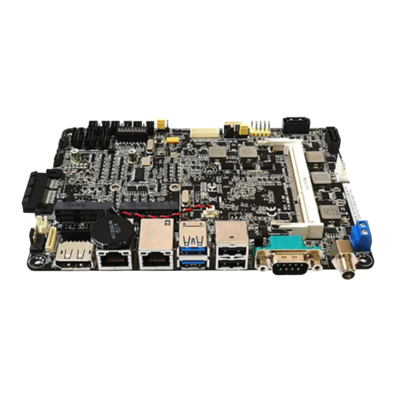
Motherboard layout NOTE: Place four screws into the holes indicated by circles to secure the motherboard to the chassis. CAUTION! Do not overtighten the screws! Doing so can damage the motherboard. 11.5cm(4.53in) PCIEX1 CLRTC1 FAY-003 DDR3L_DIMM_A1 (64bit, 204-pin module) 16MB BIOS Place this side towards the rear SPI1 of the chassis HDMI1 1442K Intel processor ® LAN1 BATTERY1 Realtek LAN2 8111G... - Page 12 Connectors/Jumpers/Slots Page Clear RTC RAM (3-pin CLRTC1) DDR3L SO-DIMM memory slot PCIe x1 slot LVDS/EDP connector (30-pin LVDSEDP) 2-14 BIOS programming header for Aaeon (8-pin SPI1) 2-14 Audio amplifier and digital audio connector (10-pin SPDIF_AMP) 2-16 USB 3.0 connectors (10-pin USB3_1, USB3_3) 2-15 LVDS panel voltage selection (10-pin LVDS_CTL) Backlight inverter power connectors (10-pin INV1, 6-pin INV2) 2-17 10. Digital I/O connector (10-pin DIO) 2-14 11. Front panel audio connector (10-pin AAFP) 2-12 12. Serial port connectors (10-pin COM2, COM34) 2-16 13. System panel connector (10-pin F_PANEL1) 2-13 14. SIM card connector (10-pin SIM1) 2-11 15. Camera Serial Interface connector (31-pin CSI1) 2-17 16. Main and standby power LEDs (LED1, LED2) 17. Serial ATA 6.0Gb/s connector (7-pin SATA6G1) 2-13 18. SATA power connector (4-pin SATA_PWR1) 2-12 19.
-
Page 13: Screw Size
Screw size 2.3.1 Component side 115.00 104.44 94.97 81.61 76.45 69.49 75.45 62.68 54.97 40.89 28.17 24.99 36.93 22.48 17.11 16.04 13.11 15.19 10.75 11.84 9.21 10.49 0.00 9.85 18.30 FAY-003... -
Page 14: Solder Side
2.3.2 Solder side 115.00 109.92 109.92 59.77 59.77 52.55 47.85 28.40 5.08 5.07 0.00 Chapter 2: Motherboard information... -
Page 15: Central Processing Unit (Cpu)
Central Processing Unit (CPU) This motherboard comes with an integrated Intel processor. ® FAY-003 Integrated Intel processor ® (Bottom) FAY-003 CPU onboard System memory This motherboard comes with one Double Data Rate 3 Low Voltage (DDR3L) Small Outline Dual Inline Memory Module (SO-DIMM) socket. The figure illustrates the location of the DDR3L DIMM socket: FAY-003 DIMM_A1 FAY-003 204-pin DDR3L DIMM socket FAY-003... - Page 16 Installing a DIMM To install a SO-DIMM To remove a SO-DIMM Chapter 2: Motherboard information...
-
Page 17: Jumpers
CLRTC1 FAY-003 Normal operation Clear CMOS (Default) FAY-003 Clear RTC RAM To erase the RTC RAM: Turn OFF the computer and unplug the power cord. Move the jumper cap from pins 1-2 (default) to pins 2-3. Keep the cap on pins 2-3 for about 5~10 seconds, then move the cap back to pins 1-2. Plug the power cord and turn ON the computer. Hold down the <Del> key during the boot process and enter BIOS setup to reenter data. - Page 18 LVDS_CTL PIN1 +V_PANEL BKLT_CTRL_VR1 VCON LVDS_PWM EDID_CLK +3V_EPROM1 EDID_DAT Pin 2-4: Set +V_PANEL to +3V (default) Pin 3-5: Set LVDS backlight control to DC mode (default) FAY-003 LVDS panel voltage selection Setting Pins Set +V_PANEL to +3V (Default) Set LVDS backlight control to DC mode (Default) Chapter 2: Motherboard information...
-
Page 19: Connectors
Data activity Green 1 Gbps connection LAN port (Blinking) Orange Ready to wake (Blinking up from S5 then steady) mode USB 3.0 port. This 9-pin Universal Serial Bus (USB) port connects to USB 3.0/2.0 devices. NOTES: • USB 3.0 devices can be used for data storage only. • Due to the design of the Intel 300 series chipset, all USB devices ® connected to the USB 2.0 and USB 3.0 ports are controlled by the xHCI controller. Some legacy USB devices must update their firmware for better compatibility. • We strongly recommend that you connect USB 3.0 devices to USB 3.0 ports for a faster and better performance from your USB 3.0 devices. USB 2.0 ports. These three 4-pin Universal Serial Bus (USB) ports are available for connecting USB 2.0/1.1 devices. COM port. This 9-pin COM port is for pointing devices or other serial devices FAY-003 2-10... -
Page 20: Internal Connectors
2.7.2 Internal connectors 12V DC power connector (2-pin DC_PWR) This port connects to a 12V DC power adapter. FAY-003 DC_PWR +12V PIN 1 FAY-003 12V DC power connector SIM card connector (10-pin SIM1) This port connects to a SIM card reader module. FAY-003 SIM1 Pin 1 UIM_DATA UIM_CLK UIM_VPP UIM_RESET UIM_PWR FAY-003 Internal SIM card connector Internal POE LAN connectors (2-pin JL1, JL2) Connect the POE LAN power cables to this connector. - Page 21 Front panel audio connector (10-pin AAFP) This connector is for a chassis-mounted front panel audio I/O module that supports HD Audio audio standard. Connect one end of the front panel audio I/O module cable to this connector. FAY-003 AAFP PIN1 MIC1_L MIC1_R LOUT_R MIC1-JD A_LOUT_L LINEOUT-JD FAY-003 Front panel audio connector IMPORTANT: We recommend that you connect a high-definition front panel audio module to this connector to avail of the motherboard’s high-definition audio capability. SATA power connector (4-pin SATA_PWR1) This connector is for the SATA power cable. The power cable plug is designed to fit this connector in only one orientation. Find the proper orientation and push down firmly until the connector completely fit. FAY-003 SATA_PWR1 Pin1 FAY-003 SATA power connector IMPORTANT: The SATA power connector supports 1A current to the maximum.
- Page 22 Serial ATA 6.0Gb/s connectors (7-pin SATA6G1) These connectors connect to Serial ATA 6.0 Gb/s hard disk drives and optical drives via Serial ATA 6.0 Gb/s signal cables. FAY-003 FAY-003 SATA 6.0Gb/s connector System panel connector (10-pin F_PANEL1) This connector supports several chassis-mounted functions. F_PANEL1 FAY-003 PIN1 HDLED+ PLED+ HDLED- PLED- POWER BTN RESET BTN FAY-003 System panel connector • System power LED (2-pin PWR_LED) This 2-pin connector is for the system power LED. Connect the chassis power LED cable to this connector. The system power LED lights up when you turn on the system power, and blinks when the system is in sleep mode.
- Page 23 HD0_CLK+ HD1_CLK+ EDP_AUXP BKLTCTL FAY-003 LVDS/EDP connector BIOS programming connector for Aaeon (8-pin SPI1) Use this connector to flash the BIOS ROM. SPI1 FAY-003 PIN 1 FAY-003 BIOS programming connector for Aaeon 10. Digital I/O connector (10-pin DIO) This connector includes 8 I/O lines (In/Out programmable). All of the Digital I/O lines are programmable and each I/O pin can be individually programmed to support various devices. FAY-003 PIN1 DIO_GP42 DIO_GP41 DIO_GP40 DIO_GP37...
- Page 24 11. mSATA / Mini PCIe x1 slot Use this connector to connect Minicard readers. MINI_CARD1 FAY-003 NUT_WLAN1 FAY-003 mSATA / Mini PCIe x1 slot NOTES: • The Mini-card module is purchased separately. • Choice between mSATA or MiniPCIe depends on customer's demand • See Appendix for rework SOP 12. USB 3.0 connectors (10-pin USB3_1, USB3_3) Connect a USB 3.0 module to any of these connectors for additional...
- Page 25 RXD2 TXD2 DTR2 TXD4 RXD4 DSR2 RTS2 CTS2 RLV_LINK_R RLV_CFG_R FAY-003 FAY-003 Serial port connectors NOTES: • The COM module is purchased separately. • These COM ports support RS-232. 14. A udio amplifier and digital audio connector (10-pin SPDIF_AMP) The upper line of pins, close to the edge of the motherboard, are for an external audio amplifier. The lower line of pins are for an additional Sony/Philips Digital Interface (S/ PDIF) port. Connect the S/PDIF Out module cable to this connector, then install the module to a slot opening at the back of the system chassis.
- Page 26 15. Camera Serial Interface connector (31-pin CSI1) This connector is for a Camera Serial Interface module. CSI1 FAY-003 FAY-003 Camera Serial Interface connector 16. Backlight inverter power connectors (10-pin INV1, 6-pin INV2) Connect the backlight inverter power cables to these connectors. INV1 PIN1 +BLVCC VCON +BLVCC INV_ENABKL +BLVCC FAY-003 INV2 FAY-003 Inverter connectors IMPORTANT: The backlight inverter power connector supports 1A current to the maximum. Chapter 2: Motherboard information...
- Page 27 17. Battery connector (2-pin BATTERY1) This connector is for the lithium CMOS battery. FAY-003 BATTERY1 PIN 1 +BAT FAY-003 Battery connector 18. M.2 E-key connector (2230_M2E) This connector is for M.2 E-key (22 x 30mm) wireless devices. 2230_M2E FAY-003 NUT_2230_M2E FAY-003 M.2 E-key connector FAY-003 2-18...
-
Page 28: Chapter 3: Bios Setup
Chapter 3 BIOS setup BIOS setup Use the BIOS Setup to update the BIOS or configure settings. The BIOS screens include navigation keys and help to guide you in using the BIOS Setup program. Entering BIOS Setup at startup To enter BIOS Setup at startup: Press <Delete>... -
Page 29: Main Menu
Be cautious when changing the settings of the Advanced menu items. Incorrect field values can cause the system to malfunction. 3.3.1 Trusting Computing Security Device Support [Enable] Allows you to enable or disable BIOS support for security devices. Configuration options: [Disable] [Enable] FAY-003... - Page 30 SHA-1 PCR Bank [Enabled] Allows you to enable or disable SHA-1 PCR Bank. Configuration options: [Enabled] [Disabled] SHA256 PCR Bank [Enabled] Allows you to enable or disable SHA256 PCR Bank. Configuration options: [Enabled] [Disabled] Pending operation [None] Allows you to schedule an operation for security devices. Reboot your system for the changes to take effect.
-
Page 31: Cpu Configuration
The USB Devices item lists auto-detected values. If no USB device is detected, the item shows None. Legacy USB Support [Enabled] [Enabled] Enables the support for USB devices on legacy operating systems (OS). [Disabled] USB devices are only available when running BIOS Setup. FAY-003... -
Page 32: Hardware Monitor
[Auto] Allows the system to detect the presence of USB devices at startup. If detected, the USB controller legacy mode is enabled. If no USB device is detected, the legacy USB support is disabled. 3.3.5 Hardware Monitor This menu displays the system/CPU temperatures and power status. 3.3.6 SIO Configuration The items in this menu allow you to configure Super IO settings. -
Page 33: Power Management
Specify the values for day/hour/minute/second. The following item appears when Wake System with Dynamic Time is enabled. Wake up minute increase [1] Specify the number of minutes added to the current time before waking up system. Input value range: [1~5] FAY-003... -
Page 34: Digital Io Port Configuration
3.3.8 Digital IO Port Configuration The items listed in this screen configure Digital IO settings. DIO Port1~Port4 [Output], DIO Port5~Port8 [Input] Configuration options: [Input] [Output] The following item appears only when you set DIO Port1~8 to [Output]. Output Level [High] Configuration options: [High] [Low] Chipset menu The Chipset menu items allow you to change configuration options for the North Bridge and South Bridge. -
Page 35: Security Menu
If you have set a user password, you must enter the user password for accessing the system. The User Password item on top of the screen shows the default Not Installed. After you set a password, this item shows Installed. FAY-003... -
Page 36: Boot Menu
To set a user password: Select the User Password item and press <Enter>. From the Create New Password box, key in a password, then press <Enter>. Confirm the password when prompted. To change a user password: Select the User Password item and press <Enter>. From the Enter Current Password box, key in the current password, then press <Enter>. -
Page 37: Save & Exit Menu
This option allows you to exit the Setup program without saving your changes. When you select this option or if you press <Esc>, a confirmation window appears. Select Yes to discard changes and exit. Restore Defaults Save or restore User Defaults to all setup options. FAY-003 3-10... -
Page 38: Appendix
Check local regulations for disposal of electronic products. DO NOT throw the mercury-containing button cell battery in municipal waste. This symbol of the crossed out wheeled bin indicates that the battery should not be placed in municipal waste. FAY-003... -
Page 39: Msata / Minipcie Rework
R456,R458 (10G212000004020 : RES 0 OHM 1/16W(0402)JUMP 5%) C425,C426 (11G232110411150 : MLCC 0.1UF/16V(0402) X7R 10%) NOTE: faytech strongly urges you not to attempt any modifications by yourself as it will lead to the termination of the warranty of the product and may damage the product itself. -
Page 40: Faqs
FAQs To be added in later versions. FAY-003... - Page 41 ○ ○ ○ ○ 外部信號連接頭 × ○ ○ ○ ○ ○ 及線材 中央處理器與內 × ○ ○ ○ ○ ○ 存 本表格依據 SJ/T 11364 的規定編制。 ○: 表示該有害物質在該部件所有均質材料中的含量均在 GB/T 26572 規 定的限量要求以下。 ×: 表示該有害物質至少在該部件的某一均質材料中的含量超出 GB/T 26572 規定的限量要求,然該部件仍符合歐盟指令 2011/65/EU 的 規范。 備註:此產品所標示之環保使用期限,係指在一般正常使用狀況下。 FAY-003...
Need help?
Do you have a question about the FAY-003 and is the answer not in the manual?
Questions and answers