Table of Contents
Advertisement
Quick Links
Specifications Information and Repair Parts Manual
Please read and save this Repair Parts Manual. Read this manual and the General Operating Instructions carefully before attempting to assemble,
install, operate or maintain the product described. Protect yourself and others by observing all safety information. The Safety Instructions are contained
in the General Operating Instructions. Failure to comply with the safety instructions accompanying this product could result in personal injury and/or
property damage! Retain instructions for future reference. AMT reserves the right to discontinue any model or change specifications at any time without
incurring any obligation.
©2015 AMT Pump Company, Subsidiary of The Gorman-Rupp Company, All Rights Reserved.
Periodic maintenance and inspection is required on all pumps to ensure proper operation. Unit must be clear of debris and sediment. Inspect for leaks and loose bolts. Failure
to do so voids warranty.
IPT Trash Pumps
Refer to pump manual 1808-633-00 for General Operating and Safety Instructions.
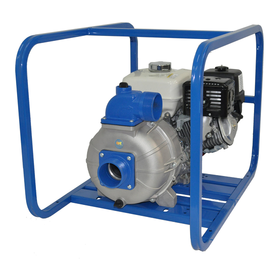
DESCRIPTION
This trash pump is a heavy duty, centrifugal, engine-driven, self-priming (to 20 ft. lift after initially filling casing with liquid),
portable unit. Pump is equipped with precision lapped mechanical seal to reduce the likelihood of leakage, and a clog-
resistant impeller capable of handling solids, 4" models up to 2" diameter. Units are used to handle water containing
stones, sticks, mud and other solids (up to 25% by volume). Sealed flange connections facilitate easy removal of suction
and discharge lines. Handles liquids from 40º to 180º F (4º to 82º C). For use with nonflammable fluids compatible with
pump component materials.
All models come standard with manual recoil starter. 4" models feature 12 VDC electric start 5" W x 7¾" L x 5" H battery
holder included. (Battery not included; obtain 12V, 32 amp hour battery from local lawn and garden shop). Pump and
engine are mounted in steel roll frame, requires minimum 2 people to move or lift. Four position discharge manifold
provides a choice in placing hose.
UNPACKING
Refer to Repair Parts Illustration and Repair Parts List to
aid in identifying parts. Unpack and separate all pump
components from container, making sure all parts are
accounted for. Packages should contain:
1.
Pump and engine completely assembled in
frame.
2.
Battery tray and battery tray hardware (E-start
models only).
3.
NPT Strainer.
ASSEMBLY
(Refer to Figure 3)
1.
Remove pump from packaging.
2.
Electric Start Models Only:
Install a 12 volt type no. 9A1 garden tractor
battery 32 amp hour rating, approx. size 7¾" L x
5" W x 6" H (not included) onto battery tray.
Using hardware included with pump, insert hook
bolts through battery tray holes, thread facing
up. Attach battery box hold down bar across
battery and thread wing nuts onto hook bolts.
3.
Refer to engine manual for proper wiring
instructions. Be sure to route and secure battery
cable safely UNDER pump where it will not be
pinched or come in contact with hot engine
exhaust or muffler (see Figure 1)
4SXX-250-00
4S13XAR, 4S13XHR, 4S10XYR & 4S10XZR
Figure 1 – Battery Cable
MAINTENANCE
MECHANICAL SEAL REPLACEMENT
(Refer to Figure 2 and 3)
Disconnect spark plug wire and battery to prevent
accidental starting.
NOTE: Always replace the seal seat (Ref. No. 8), seal
head (Ref. No. 9) and shaft sleeve (Ref. No. 10) to
ensure proper mating of mechanical seal components!
1
10/2015
Advertisement
Table of Contents

Related Manuals for AMT 4S13XAR


Summary of Contents for AMT 4S13XAR
- Page 1 General Operating Instructions. Failure to comply with the safety instructions accompanying this product could result in personal injury and/or property damage! Retain instructions for future reference. AMT reserves the right to discontinue any model or change specifications at any time without incurring any obligation.
- Page 2 Specifications Information and Repair Parts Manual 4S13XAR, 4S13XHR, 4S10XYR & 4S10XZR IPT Trash Pumps Apply a light coating of soapy water to the inside rubber portion of seal head and slide onto the shaft sleeve. Slip the shaft sleeve with seal head onto the engine shaft.
- Page 3 Specifications Information and Repair Parts Manual 4S13XAR, 4S13XHR, 4S10XYR & 4S10XZR IPT Trash Pumps IMPELLER AND WEARPLATE CLEANING REPLACEMENT These units are designed so that for most cleanout or clogging problems it should not be necessary to remove Impeller (Ref. No. 12) and volute/wear plate (Ref. No.
- Page 4 Specifications Information and Repair Parts Manual 4S13XAR, 4S13XHR, 4S10XYR & 4S10XZR IPT Trash Pumps For Repair Parts contact dealer where pump was purchased. Please provide following information: -Model Number -Serial Number (if any) -Part/Kit Description and Number NOTE: Parts are available only in kits listed, parts are not available individually.
-
Page 5: Repair Parts List
Specifications Information and Repair Parts Manual 4S13XAR, 4S13XHR, 4S10XYR & 4S10XZR Repair Parts List Ref. Part Number of Model Description 4S13XAR 4S13XHR 4S13XZR 4S10XYR Qty. Engine 1639-005-00 1639-031-00 1630-050-00 1639-039-00 Shaft Flange 3923-140-09 3923-140-09 3923-140-09 3923-140-09 Lock Washer Hex Head Cap Screw... - Page 6 Specifications Information and Repair Parts Manual 4S13XAR, 4S13XHR, 4S10XYR & 4S10XZR NOTES: 4SXX-250-00 10/2015...
- Page 8 www.amtpump.com...
Need help?
Do you have a question about the 4S13XAR and is the answer not in the manual?
Questions and answers